
Schematic Audio Amplifier Circuit With NCC200 Transistor
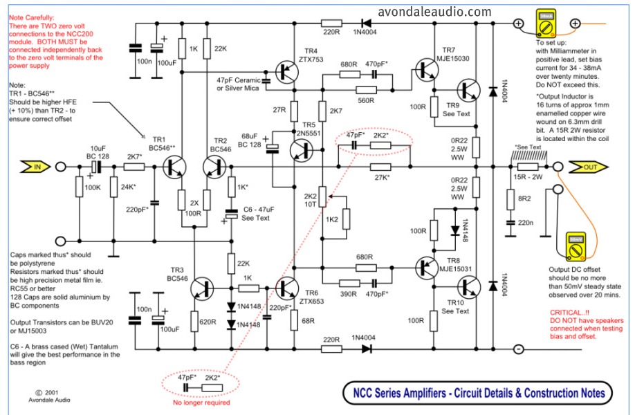
The described circuit utilizes high-performance power amplifiers, which are essential for applications requiring significant signal amplification. The PCB (Printed Circuit Board) design facilitates easy assembly and integration into various electronic systems.
The power amplifier circuit typically includes several key components: transistors or operational amplifiers that serve as the main amplification elements, resistors for biasing and feedback, capacitors for filtering and stability, and possibly inductors for additional tuning or load matching.
The layout of the PCB is critical to ensure optimal performance; it must minimize parasitic inductance and capacitance while providing adequate heat dissipation for the power components. The choice of materials for the PCB, such as FR-4 or other low-loss substrates, can also impact the performance characteristics of the amplifier.
In addition to the main amplification components, the circuit may include input and output connectors, power supply circuitry, and protection mechanisms such as fuses or thermal shutdown features to prevent damage to the amplifier under overload conditions.
This power amplifier circuit is suitable for a variety of applications, including audio amplification, RF transmission, and signal conditioning in instrumentation systems. The availability of a complete list of parts simplifies the assembly process, allowing engineers and hobbyists to quickly source the necessary components for their projects.This is a simple circuit but have a high performance power amplifiers. This power amplifier is available as a PCB, with full list of parts to .. 🔗 External reference
Related Circuits
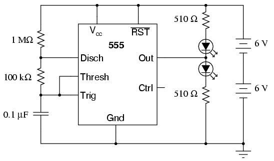
The 555 integrated circuit is a versatile timer that can be used for various applications. This experiment focuses on its operation as an astable multivibrator or oscillator. When connected to a capacitor and two resistors, it generates a square-wave...
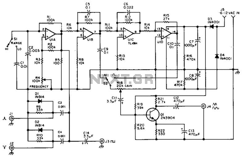
A quad op-amp serves as the core component of this function generator. U1A produces a square wave, which is outputted to J8. J1 and J2 are pulse outputs derived from differentiating the square wave. The integrator U1B creates a...
The digital scoreboard circuit is designed to display numerical values ranging from 0 to 9 on a common anode 7-segment display. The circuit employs a 7-segment driver integrated circuit (IC), specifically the 74LS47 or 74LS247. A 555 timer IC...
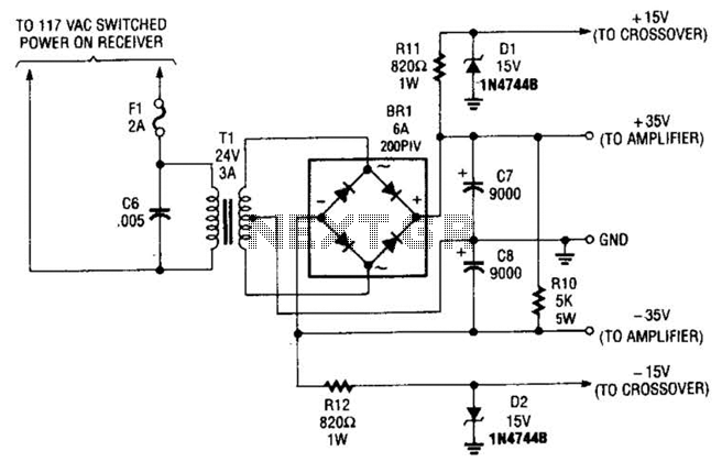
This power supply is designed to power a 100-W low-frequency amplifier and is capable of supporting various mono or stereo amplifiers within the medium power range, specifically those that require 30 to 35 V. The power supply circuit is engineered...
A small signal amplifier, perhaps of the type to follow the previous buffer amplifier. We will assume we are buffering and amplifying our signal from the voltage controlled oscillator tutorial. In those examples we were generating and buffering 1.8...
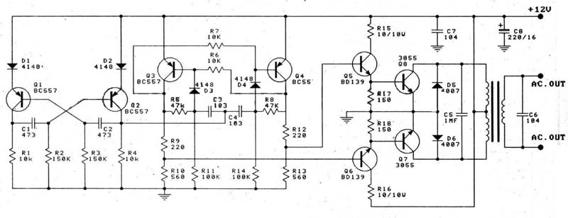
A 12V car battery is recommended as the input for this circuit, utilizing the 2N3055 transistor as the amplifier. This configuration can deliver a power output of up to 100W, making it suitable for use in battery chargers, emergency...