
digital scoreboard circuit
The digital scoreboard circuit is structured to provide a clear and efficient display of numerical values through the utilization of a 7-segment display configured in a common anode arrangement. The 74LS47 or 74LS247 driver IC is responsible for translating the binary output from the 74LS192 counter into the appropriate signals needed to illuminate the segments of the display, allowing for a visual representation of the counted values.
The 555 timer IC plays a crucial role in generating a precise clock signal that drives the counting process of the 74LS192, which is a synchronous binary counter capable of counting both upwards and downwards. The inclusion of three switches enhances the functionality of the circuit: switch S1 allows for an increment in the count, effectively increasing the displayed number, while switch S2 permits a decrement, thereby reducing the displayed value. Switch S3 serves as a reset mechanism, returning the counter to its initial state.
The power supply voltage of 9 volts is essential for the proper operation of the entire circuit, ensuring that all components receive adequate power for optimal performance. The design of the digital scoreboard circuit is straightforward yet effective, making it suitable for various applications where numerical display and counting are required. The schematic for the digital scoreboard illustrates the interconnections between the components, providing a clear guide for assembly and troubleshooting.Digital scoreboard circuit functions to display values from 0 to 9 on the 7 segment display. 7 segments using a type of common anode. 7 segment driver IC using a 74LS47 or 74LS247. On the digital scoreboard circuitry uses a 555 timer ic, serves to produce a rate as to enter the 74LS192 counter IC. Digital scoreboard circuits there are 3 switches, if the switch S1 is pressed then the 74LS192 will calculate forward. whereas if the switch S2 is pressed then the 74LS192 will count down. to switch S3 serves to return the counter value. Source voltage on the digital scoreboard is 9 volts. Here is a schematic drawing digital scoreboard: 🔗 External reference
Related Circuits
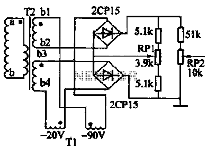
The closed-loop system consists of longitudinal and transverse components. The circuit operates as follows: a control circuit from the stepping motor CNC system issues a command, which the receiver detects. This signal is processed through a phase-sensitive rectifier to...
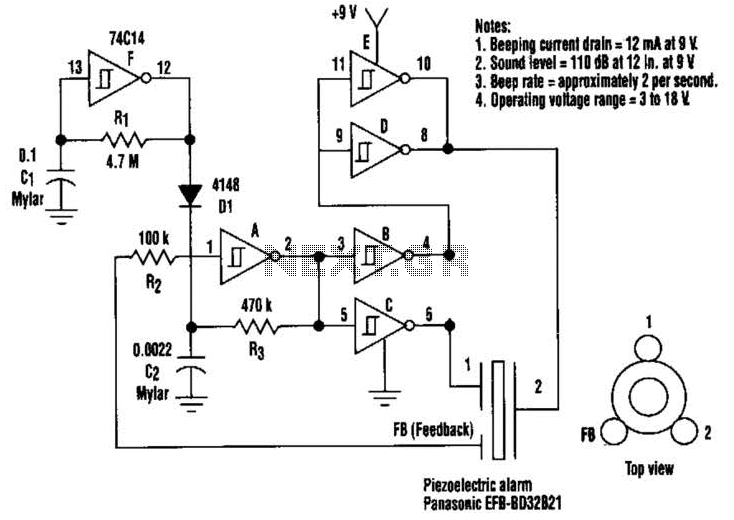
This circuit generates a loud sound of 110 dB using a 9 V power supply. It incorporates a single 74C14 (CD40106B) CMOS hex inverting Schmitt-trigger IC, which is utilized with a piezoelectric device that includes a feedback terminal. The...
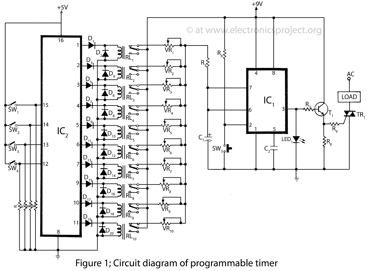
The programmable timer presented on this website is a straightforward design utilizing only two integrated circuits (ICs). It covers a wide range of applications and includes descriptions of various timer projects. The programmable timer circuit typically consists of two primary...
This document presents an intriguing collection of frequency dividers with division factors ranging from 2 to 10. All options are based on the 7490, which is a decade and binary counter. The frequency dividers utilizing the 7490 integrated circuit (IC)...
Servo motors are utilized in various applications, including robotics, puppetry, photography, and more. These compact motors can adjust their output shaft to a specified position on command and maintain that position. Most servos offer a range of motion of...
SPI Integrated Circuit Bus, IC Buses, an IC, Chip-to-Chip Bus Serial Peripheral Interface, Integrated Circuit Bus types, and IC Bus Electrical Interface Descriptions. The Peripheral Interface (SPI) circuit is a. The Serial Peripheral Interface (SPI) is a synchronous serial communication...
Warning: include(partials/cookie-banner.php): Failed to open stream: Permission denied in /var/www/html/nextgr/view-circuit.php on line 713
Warning: include(): Failed opening 'partials/cookie-banner.php' for inclusion (include_path='.:/usr/share/php') in /var/www/html/nextgr/view-circuit.php on line 713