


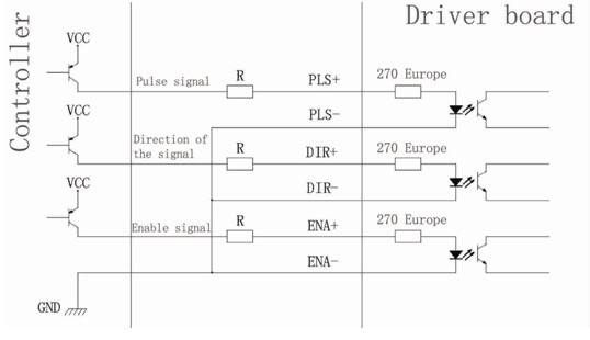
Single Axis TB6560 3 5A 2 Phase CNC Stepper Motor Driver Board Controller
#stepper motor
#TB6560
#CNC
#motor driver
#2-phase
#controller
#parallel connection
#series connection
#high-speed
#current control
Description: Connection of a drive and a two-phase hybrid stepper motor using a four-wire system, with the motor windings configured in both parallel and series connections. This method allows for high-speed performance, although it requires a large drive current (1.73 times the motor winding current). When connected in series, the drive current matches the motor winding current.
The connection of a drive to a two-phase hybrid stepper motor utilizing a four-wire system is a common practice in industrial and robotics applications. In this configuration, each of the motor's two phases is driven independently, allowing for precise control of the motor's position and speed. The motor windings can be arranged in parallel or series, depending on the desired performance characteristics.
When the windings are connected in parallel, the system benefits from increased torque and lower inductance, which can enhance the motor's responsiveness and acceleration. However, this configuration also requires a higher drive current, approximately 1.73 times the rated winding current of the motor. This increased current demand can lead to higher power dissipation in the drive circuitry, necessitating careful thermal management.
Conversely, when the windings are connected in series, the drive current is limited to the rating of the motor winding, which can simplify the design and reduce the thermal burden on the drive. In this arrangement, the motor operates at a lower overall current, but the torque may be reduced compared to the parallel configuration. The series connection is particularly advantageous in applications where space is limited or where the drive circuitry must be minimized.
Both connection methods offer unique advantages and trade-offs that must be considered based on the specific requirements of the application. Proper selection of the connection type, alongside appropriate drive circuitry capable of handling the required current levels, is essential for optimizing the performance of the stepper motor in its intended use case.Drive and two-phase hybrid stepper motor`s connection with the four-wire system, the motor windings in parallel and series connection, and connection method, high-speed performance, but the drive current is large (for motor winding current of 1. 73 times), Connected in series when the drive current is equal to the motor winding current.
The connection of a drive to a two-phase hybrid stepper motor utilizing a four-wire system is a common practice in industrial and robotics applications. In this configuration, each of the motor's two phases is driven independently, allowing for precise control of the motor's position and speed. The motor windings can be arranged in parallel or series, depending on the desired performance characteristics.
When the windings are connected in parallel, the system benefits from increased torque and lower inductance, which can enhance the motor's responsiveness and acceleration. However, this configuration also requires a higher drive current, approximately 1.73 times the rated winding current of the motor. This increased current demand can lead to higher power dissipation in the drive circuitry, necessitating careful thermal management.
Conversely, when the windings are connected in series, the drive current is limited to the rating of the motor winding, which can simplify the design and reduce the thermal burden on the drive. In this arrangement, the motor operates at a lower overall current, but the torque may be reduced compared to the parallel configuration. The series connection is particularly advantageous in applications where space is limited or where the drive circuitry must be minimized.
Both connection methods offer unique advantages and trade-offs that must be considered based on the specific requirements of the application. Proper selection of the connection type, alongside appropriate drive circuitry capable of handling the required current levels, is essential for optimizing the performance of the stepper motor in its intended use case.Drive and two-phase hybrid stepper motor`s connection with the four-wire system, the motor windings in parallel and series connection, and connection method, high-speed performance, but the drive current is large (for motor winding current of 1. 73 times), Connected in series when the drive current is equal to the motor winding current.
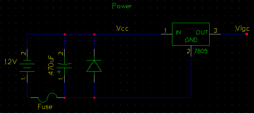
Bipolar Stepper Motor Driver Circuit
The circuit operates by using a clock signal to drive four D-flip-flops in the control section, which store the on/off state of each current direction for the two stepper motor coils. The flip-flops create a finite state machine (FSM) that...
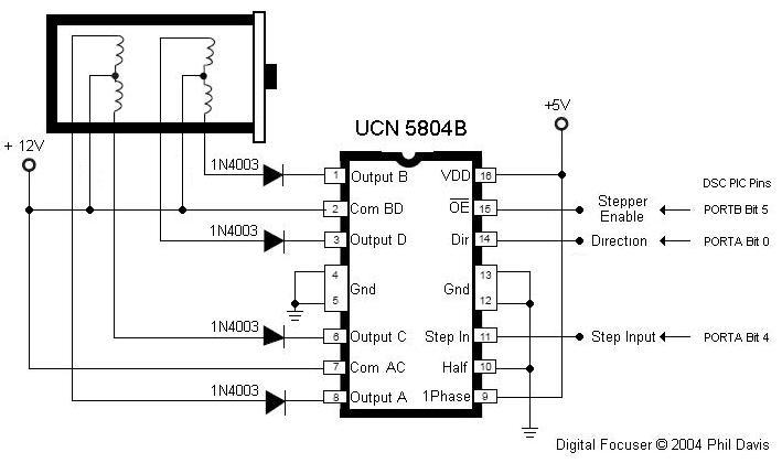
Focusser
Create an electronic focuser to assist with astrophotography. This electronic focuser project enables precise focusing under computer control, which is particularly beneficial for eyepiece projection astrophotography. It was observed that even minor contact with the focuser could displace the object...
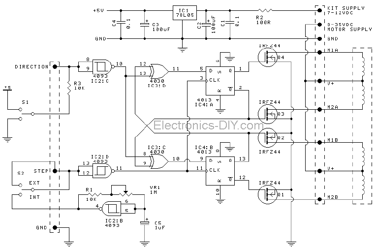
Stepper Motor Driver
These motors consist of two coils and are operated by altering the direction of current flow through the coils in a specific sequence. They feature only four wires and cannot be directly connected to this kit. Refer to Kit 1406...
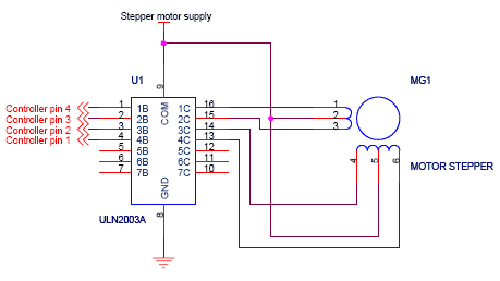
stepper motor interfacing connections
Stepper motor interfacing with a microcontroller. Full-step and half-step stepper control. Working principles and basics of stepper motors. Tutorial on 6-lead unipolar stepper motors and bipolar stepper motors.
Stepper motors are widely used in various applications requiring precise control of angular...
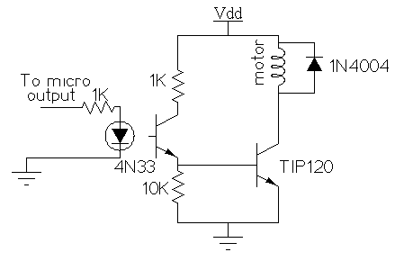
spider
The spider prop has a straightforward mechanical setup, but its electronic configuration is more complex. It utilizes a stepper motor, which requires a controller, such as a computer or microcontroller, to operate effectively. Stepper motors do not simply turn when...
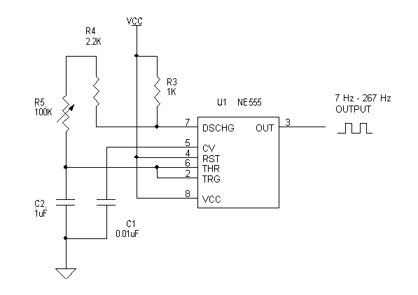
stepper motor tester
To build a stepper motor tester, the circuit includes two sets of drivers that support both unipolar and bipolar stepper motors. The control circuit and driver circuit are powered by separate supplies, allowing compatibility with a wider range of motor...
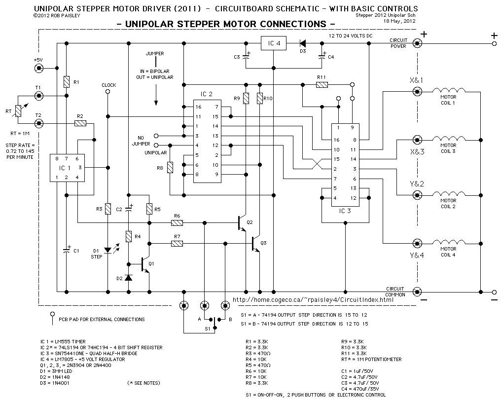
Stepper Motor Driver Circuit
The following diagram is for the main circuit of the motor driver. A testing version is shown near the end of this page. It is laid out differently and shows the SN7474 in logic block form and LEDs are used...
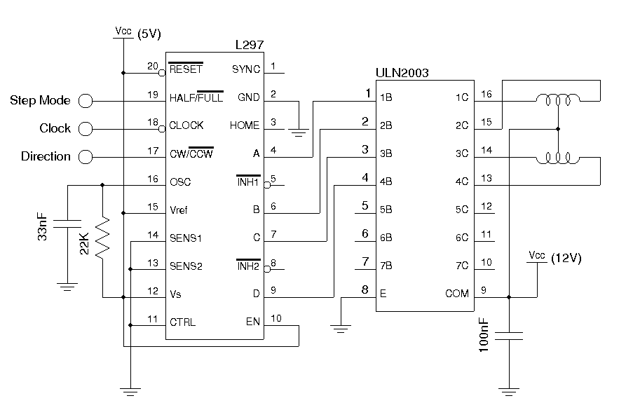
A Unipolar Stepper Motor Driver
The drive circuits for unipolar stepper motors are typically straightforward. In their simplest configuration, a transistor or MOSFET is employed to control each section of the windings. The control signal must be supplied programmatically to the four windings of the...
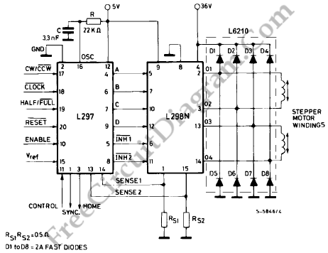
l297 stepper motor controller circuits
The L29 Stepper Motor Controller IC facilitates the control of four drive signals for two bipolar and four unipolar footfall motors in a microcomputer-controlled appliance. It allows for motor operation in half-step, full-step, and wave drive modes, utilizing switch-mode control...