
HV Ignition Coil Driver using 555

WARNING: This can kill smaller animals, such as cats and rabbits, and probably even small children! For a much safer electric fence, please consider making the "C-Mos Fencer" project. However, this car coil design can have many other uses as a high voltage supply.
This circuit utilizes the popular 555 timer IC in astable mode to generate a continuous pulse output. The 555 timer is configured to oscillate at a frequency that is suitable for driving a car ignition coil, which is capable of generating high voltage. The output of the 555 timer is connected to the primary winding of the ignition coil, causing it to produce a high-voltage pulse at its secondary winding.
The design includes a few key components: resistors and capacitors that determine the frequency of the oscillation, as well as a diode to protect the circuit from back EMF generated by the ignition coil. The output voltage from the secondary winding can reach thousands of volts, which is sufficient for creating an electric fence that deters animals from entering the protected area.
The high voltage wire should be securely mounted 3 inches above the ground using homemade PVC pipe insulators, which will prevent unintended grounding and ensure effectiveness. It is crucial to follow safety precautions when working with high voltage circuits, as improper handling can result in serious injury or death, particularly to small animals and children.
While the design is effective for deterring small animals, it is imperative to consider alternative designs, such as the "C-Mos Fencer," for a safer electric fence solution. This circuit can also be repurposed for other applications requiring a high voltage supply, making it a versatile addition to an electronics engineer's toolkit.A Simple design based on a 555 to Drive a Car Ignition Coil. I Designed this for a Small Electric Fence to Protect my Vegitable Garden from some Small Animal called a Marmots. Last year they ate one of my crops entirely before I could install this device. A Few Shocks and No More Probem. My Garden is on Raised beds and the High Voltage wire is just 3 inches above the wood frames on homemade PVC Pipe Insulators.
Could be Quite useful for persons that have Rabbit Problems also, with the wire raised a bit higher, But Read Warning Below. Definately Makes a STRONG Electric Fence. However, because it is a Continuous pulse output, WARNING: This can Kill Smaller animals, such as cats and rabbits, And Probably Even Small Children! For a Much Safer Electric Fence, PLEASE consider making the "C-Mos Fencer" Project. However this Car coil design can have many other uses as a HV Supply. 🔗 External reference
Related Circuits
The following circuit is a basic 555 square wave oscillator. Features include a 1 kHz tone, simple circuitry, a current limit of 200 mA, reduced inductive voltage, and a supply voltage range of 4.5 to 9 volts. Components used...
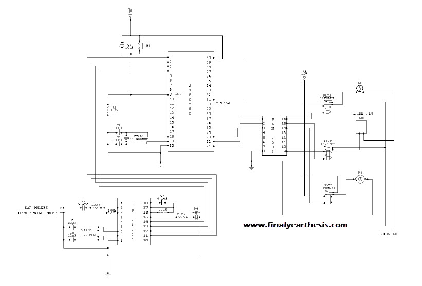
The objective of the project is to create a system that utilizes mobile technology to manage various home appliances based on signals sent from a mobile device. This innovative concept allows for the remote control of appliances through GSM...

The TEA5551T monolithic integrated radio circuit can be utilized to design an AM radio receiver, intended for use as a portable radio receiver with headphones. The TEA5551T radio receiver circuit encompasses all necessary components for a complete AM receiver,...

This design circuit is a tone control circuit that utilizes the popular Baxandall configuration, a straightforward circuit layout that allows for continuous boost and cut control. The circuit is inexpensive to construct and is frequently implemented in commercial products....
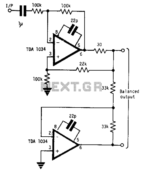
This circuit will handle +24 dBm with ± 12 volts supply using TDA 1034s. This circuit uses current and voltage feedback. The described circuit utilizes the TDA 1034S integrated circuit, which is designed for audio applications and can handle an...
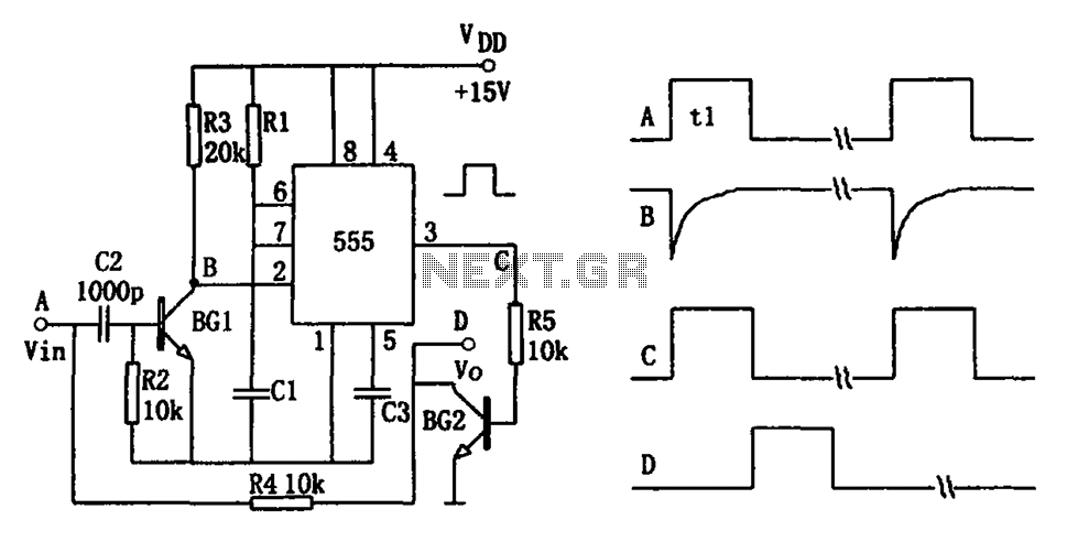
The pulse-width detection circuit is illustrated in the figure and consists of a differential circuit (R2, C2), an amplifier (BG1), a single stabilizing circuit (555, R1, C1), and various other components. The pulse signal Vin (depicted as waveform A)...