
Triangular Wave Generator
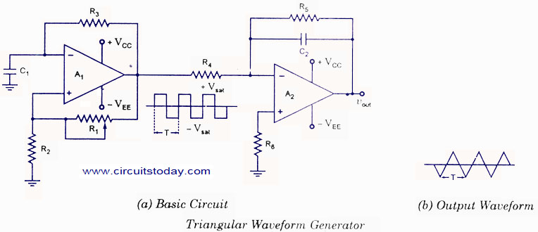
The triangular wave generator circuit typically employs an op-amp in an integrator configuration. The fundamental principle involves generating a square wave signal, which is then fed into the input of the integrator circuit. The op-amp integrates this square wave, producing a triangular wave output.
In the circuit, the op-amp is connected with feedback that includes a capacitor and a resistor. The square wave input is applied to the non-inverting terminal of the op-amp. The integration process occurs as the op-amp outputs a voltage that ramps up and down, corresponding to the square wave's high and low states. The output voltage increases linearly during the positive half-cycle of the square wave and decreases linearly during the negative half-cycle, resulting in a triangular waveform.
The frequency of the triangular wave is determined by the frequency of the input square wave and the RC time constant, which is defined by the resistor and capacitor values in the feedback loop. Adjusting these components allows for the tuning of the triangular wave's characteristics, including its amplitude and frequency.
To construct a practical triangular wave generator, a suitable op-amp such as the LM741 can be used. The circuit should also include power supply decoupling for stability and noise reduction. The output can be further processed or utilized in various applications, such as waveform generation for signal processing, modulation, or testing purposes.
In summary, the triangular wave generator circuit based on an op-amp provides a reliable method for generating triangular waveforms through the integration of square wave signals, with practical applications across various electronic systems.Triangular wave generator using opamp. Circuit diagram theory and working. Integrating square wave produces a triangular wave. Practical circuit diagram of triangular wave generator.. 🔗 External reference
Related Circuits
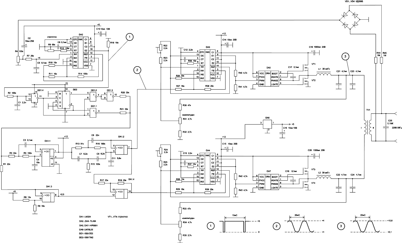
In DA3, DA5, VT1, and VT2, the first channel of the VLF Class D amplifier is assembled. The second channel is constructed using DA4, DA7, VT3, and VT4. Antiphase sine waves in the VLF range are formed at the...
This circuit is based on the State Variable Band Pass Filter, incorporating amplitude-limited regenerative feedback. The State Variable Band Pass Filter (SVBPF) is a versatile filter design that allows for simultaneous control over the center frequency, bandwidth, and gain. This...
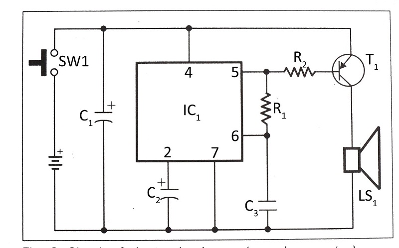
This document presents a verified circuit diagram for a simple, interesting, and cost-effective electronic clapper (sound generator) circuit, along with a description of its functionality. The electronic clapper circuit is designed to activate sound generation through the detection of sound...
A type of relaxation oscillator comprising two stages that are interconnected such that the input of one stage is derived from the output of the other. This configuration essentially consists of two amplifiers cross-coupled with regenerative feedback in its...
If you have ever wanted a high-voltage generator to create impressive lightning effects, conduct Kirlian photography experiments, or experiment with neon lights, this project is ideal. It describes a laboratory pulse generator utilizing an auto-ignition coil, capable of delivering...
The Tri-Waveform Generator can be used for a number of different uses. The one that I use it for is a signal generator to test circuits. The frequency range is 20 to 20kHz and can be adjusted by R1....