
Ultrasonic Sensor Circuit

The ultrasonic sensor circuit is an effective tool for measuring distances in various applications, including robotics, automotive systems, and industrial automation. The design typically includes several key components: a piezoelectric transducer, an oscillator, an amplifier, and a microcontroller or comparator for processing the signals.
The piezoelectric transducer serves dual roles in this circuit; it acts as both the transmitter and receiver of ultrasonic waves. The oscillator generates a high-frequency signal, which is fed into the piezoelectric transducer, causing it to emit ultrasonic waves. The frequency of the oscillator is critical; it must be tuned to the resonant frequency of the transducer to maximize efficiency and sensitivity.
When the ultrasonic waves encounter an object, they are reflected back toward the sensor. The receiver, also a piezoelectric transducer, detects these reflected waves. The time taken for the waves to return is measured, allowing the circuit to calculate the distance to the object using the formula \( s = vt \), where \( s \) is the distance, \( v \) is the speed of sound, and \( t \) is the time of flight.
The amplifier boosts the received signal, making it easier for the microcontroller or comparator to process. The comparator can be programmed to trigger specific actions based on the measured distance, making the system adaptable for various applications, such as obstacle detection in autonomous vehicles or level sensing in tanks.
In summary, the ultrasonic sensor circuit is a sophisticated system that leverages the principles of sound wave propagation and piezoelectricity to perform accurate distance measurements. Its versatility and non-contact measurement capability make it an invaluable component in many modern electronic applications.Ultrasonic sensor circuit is a sensor that consists of transmitter and receiver. This circuit is useful for remote control. The frequency of sound produced by a series of Ultrasonic Sensor is above 20 KHz which is between 40 KHz 50 KHz. Used power supply voltage is 9 V battery cans so use with a voltage of 9 V. How it works is a series of ultr asonic sensors in the circuit if the switch is pressed then the transmitter will from send signals received by the receiver circuit. Ultrasound acoustic wave having a frequency of 20 kHz to about 20 MHz. The Following is a schematic drawing: where s is the distance in units of meters, v is the speed of sound is 344 m / s and t is the travel time in seconds.
While most obstacles ultrasound waves are reflected partly absorbed and some other people will be continued. Ultrasonic sensor is a sensor that changes the physical quantities (sound) to the amount of electricity.
In this case an ultrasonic wave sensor generated through an agency called piezoelectric. This will produce piezoelectric ultrasonic waves with a frequency of 40 kHz when an oscillator is applied to the object. Ultrasonic sensors typically used for a disclosure does not touch such a variety of measurement applications.
This tool is generally emit ultrasonic sound waves toward the target that reflects the waves back toward the sensor. The system measures the time required for the transmission of waves to go back and calculate the distance to the target sensor by using the speed of sound in the medium.
Compiler series ultrasonic sensor consists of transmitter, receiver, and comparator. In addition, ultrasonic waves generated by a thin piezoelectric crystals. Direct piezoelectric equipment change electrical energy into mechanical energy. Input voltage causes a ceramic that is used to stretch and emit ultrasonic waves. Type of transmission operations in around 32 kHz frequency piezoelectric elements. Better efficiency, if the oscillator frequency is set at the piezoelectric resonance frequency with the best sensitivity and efficiency. If the pulse measuring mode the circuit operates on the same piezoelectric element can be used as a transmitter and receiver.
The resulting frequency depends on the operating frequency of the oscillator was adjusted from each transducer. Because of this advantage is more suitable for piezoelectric transducers ultrasonic sensors. Transmitter is a device that functions as an ultrasonic wave transmitter with a frequency of 40 kHz is generated from an oscillator.
To produce frequency 40 KHz, to make the oscillator circuit and the output of the oscillator signal and hold amplifier. The number of frequency components is determined by the prop RLC / crystal oscillator, depending on the design used.
Signal amplifier will provide electrical signals in the feedback to the piezoelectric and mechanical reactions that vibrate and emit the appropriate frequency oscillator. Recipient consists of ultrasonic transducers using piezoelectric material, which serves as the recipient of reflection waves from the transmitter worn on the surface of an object or a wave of direct LOS (Line of Sight) from the transmitter.
Because the piezoelectric material has a reversible reaction, a ceramic element to generate electrical voltage when the wave came with resonant frequency and will vibrate the piezoelectric material. 🔗 External reference
Related Circuits

RTD sensors are measured using a precision 24-bit analog-to-digital converter (A/D) that includes a built-in programmable gain amplifier. The connections for 2-wire, 3-wire, and 4-wire RTDs are illustrated. This setup facilitates the connection and measurement of RTDs with amplifiers and...
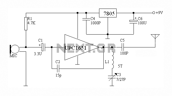
The circuit depicted utilizes the UPC1651 integrated circuit produced by NEC Corporation of Japan. It offers high gain and stability, ensuring optimal performance for microphones. The design incorporates an FM transmitter circuit. The system employs a flexible antenna measuring...

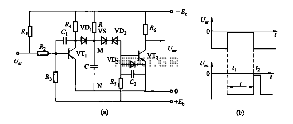
The circuit connection is illustrated in figures a and b. In figure a, a star-shaped winding is used with shunt capacitance, while figure b depicts a triangular winding with capacitance connected in parallel. The working capacitance (Cc) is calculated...
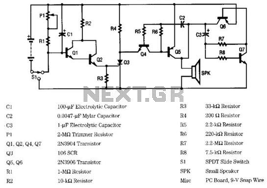
This ultra wide range timer utilizes a 555 timer as its core component, along with two 4017 decade counters and a 4020 binary counter that function as frequency dividers, which can be selectively switched in and out. Additionally, the...
The circuit features a delay action with an instantaneous reset control mechanism. It is categorized into three types: a conducting pipe rechargeable delay circuit, a tube cut-off control rechargeable delay circuit, and a discharge-type delay circuit. In the conducting...
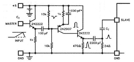
The UC3842, UC3843, UC3844, and UC3845 series of oscillators can generate synchronization pulses without requiring numerous external components. The following circuit illustrates the Sync Pulse Generator Circuit Diagram for the UC3842/3/4/5. This sync pulse circuitry is capable of operating...