
RTD Amplifier Circuit (A/D)
")
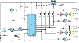
RTD (Resistance Temperature Detector) sensors are widely utilized for temperature measurement due to their accuracy and stability. The precision 24-bit A/D converter enhances the resolution of the measured signals, allowing for fine detection of temperature changes. The built-in programmable gain amplifier is crucial as it adjusts the signal level to optimize the A/D conversion process, particularly when dealing with low-level signals that may be generated by RTDs.
In terms of wiring configurations, RTDs can be connected in three different ways: 2-wire, 3-wire, and 4-wire. The 2-wire configuration is the simplest but is prone to errors due to lead resistance. The 3-wire configuration compensates for lead resistance, making it more accurate than the 2-wire setup. The 4-wire configuration is the most accurate, as it eliminates the effects of lead resistance entirely by using separate pairs of wires for the current supply and voltage measurement.
The integration of amplifiers and data acquisition systems with RTD sensors allows for enhanced measurement capabilities. Amplifiers can boost the output signal from the RTD to a level suitable for processing by the A/D converter, while data acquisition systems can digitize the signal for further analysis and monitoring. This combination is essential in applications where precision temperature measurement is critical, such as in industrial processes, HVAC systems, and laboratory environments.
Overall, the use of a precision 24-bit A/D converter, along with a programmable gain amplifier and various RTD connection configurations, provides a robust solution for accurate temperature measurement and monitoring in diverse applications.RTD sensors are measured with a precision 24-bit A/D (analog to digital converter) with built-in programmable gain amplifier. Connections for 2-wire RTDs, 3-wire RTDs, and 4-wire RTDs are shown. Connecting and measuring RTDs with amplifiers and data acquisition systems. Precision RTD resistance measurement.. 🔗 External reference
Related Circuits
This schematic illustrates a highly sensitive microphone preamplifier circuit designed to amplify the gain of a microphone or enhance audio signals originating from a microphone. The circuit is straightforward, comprising only a few components, and can be assembled in...
This circuit is designed for use in a hi-fi showroom, allowing for the selection of different speakers to connect to a stereo amplifier for comparative listening. It can also serve similar applications where only one device from a set...
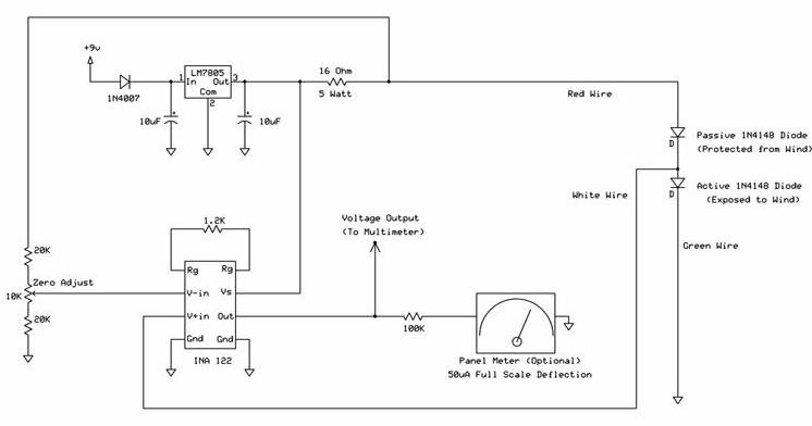
The following circuit illustrates a wind speed indicator circuit. It operates with a constant 5 VDC output provided by the LM7805 voltage regulator, using a 9 VDC supply. The wind speed indicator circuit is designed to measure and display wind...
This circuit is designed to indicate when a plant requires watering. An LED blinks at a low frequency when the soil in the flower pot is excessively dry, turning off as the moisture level rises. The sensitivity of the...
Controlled by indoor and outdoor temperature, this circuit features a simple and highly reliable design. It is intended to control a heating system or central heating plan. The described circuit functions as a temperature control system, integrating both indoor and...
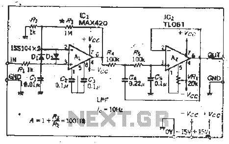
The MAX420 is a monolithic chopper operational amplifier with a supply voltage of 15 V (ICL76s0 supply voltage of 15 V), exhibiting favorable input characteristics. The input offset voltage is 1 mV. Additional specifications include an input drift of...