
Voltage Regulator Using Zener Diode Circuit
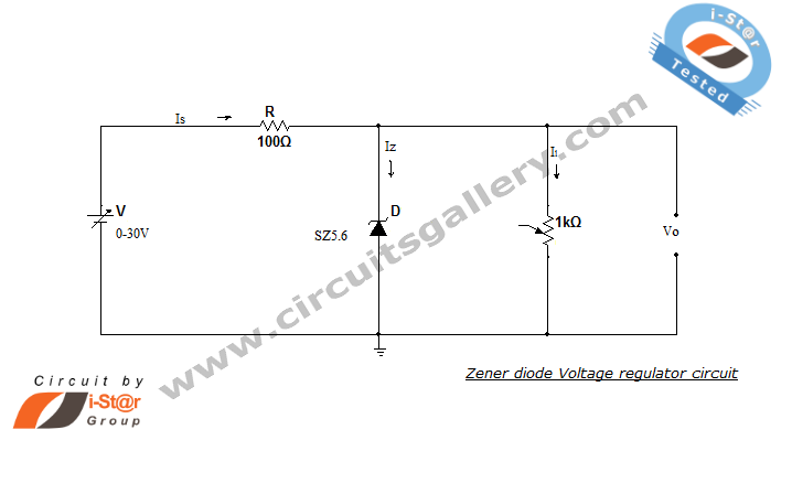
The Zener diode voltage regulator circuit typically includes a Zener diode connected in parallel with the load and a series resistor that limits the current flowing through the Zener diode. The resistor is crucial as it determines the maximum current that can flow through the Zener, ensuring that it operates within its specified limits. When designing this circuit, it is essential to select a Zener diode with a breakdown voltage that matches the desired output voltage. The series resistor value can be calculated using Ohm's law and the Zener diode specifications, taking into account the maximum input voltage and the desired load current.
In operation, when the input voltage is applied, the Zener diode enters the breakdown region and clamps the output voltage to its specified value. This regulation occurs as long as the current through the Zener remains above the minimum required level. If the load draws more current than the Zener can supply while remaining in breakdown, the output voltage will drop, indicating a failure in regulation. Therefore, proper sizing of the resistor and selection of the Zener diode are critical for ensuring reliable performance.
Additionally, the circuit's performance can be affected by temperature variations, as the Zener voltage can drift with temperature changes. It is advisable to consider temperature coefficients when selecting Zener diodes for precision applications. Overall, the Zener diode voltage regulator is a simple yet effective solution for providing stable voltage in various electronic applications, particularly in low-power scenarios where minimal components are desired.Zener diode regulator is a basic electronic circuit which is very useful for those interested in hobby circuits. This circuit is used for obtaining a regulated voltageat the output which can be used for biasing other circuit elements.
Now how to use zener diode as voltage regulator When zener is in reverse breakdown region, the zener voltage remai ns almost constant irrespective of the current through it. The major benefit of using zener diode as a voltage regulator is that it helps us to avoid the bulky&costly DC source to a great extend. Now lets see how to make a ZENER VOLTAGE REGULATOR. The circuit only contains a zener diode and passive electronic element- resistor. Active source is provided for power supply to the circuit. Zener voltage regulator is also known as Zener voltage limiter due to its voltage regulation property irrespective of the current through the zener diode.
If input voltage decreases, IL remains the same. Iz &Is decreases. If Iz falls lower than minimum zener current required to keep the Zener in breakdown region, the regulation will stop and voltage at output will decrease. 🔗 External reference
Related Circuits
This circuit operates on 12V DC instead of mains AC. This is an advantageous approach for those who prefer not to deal with circuits connected directly to mains voltage or wish to power the stroboscope using batteries. Flash Slave...
This AC motor speed controller can handle most universal type (brushed) AC motors and other loads up to about 250W. It works in much the same way as a light dimmer circuit; by chopping part of the AC waveform...
If a negative supply is required for an operational amplifier or if a negative bias voltage is needed while operating from a single supply voltage, such as in battery applications. To generate a negative supply voltage from a single positive...
A circuit is required where, upon power application, a timer triggers, keeping a relay in the off state. Once the timer completes its cycle, the relay will activate. The circuit design consists of a timer integrated with a relay to...
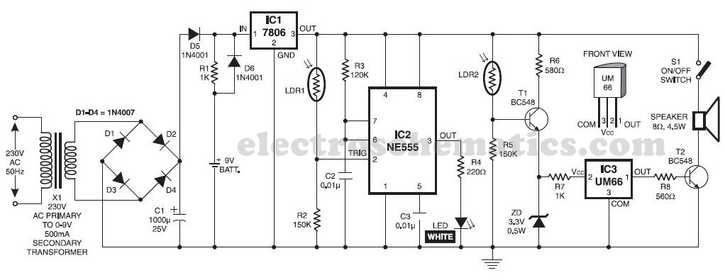
This musical light alarm circuit is very simple and uses only seven components, including a light-dependent resistor (LDR) and a 3.6V battery or three 1.2V rechargeable batteries. The well-known UM66 is utilized as the sound generator, providing a pleasant...
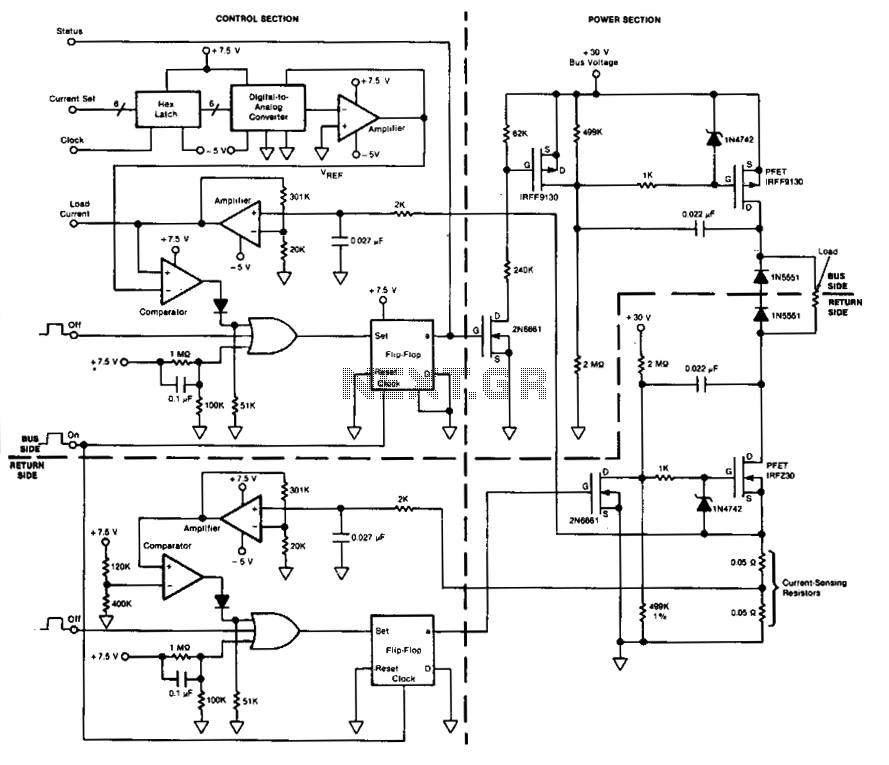
This circuit facilitates on/off switching, soft starting, current monitoring, current tripping, and overcurrent protection for a 30 Vdc power supply, accommodating normal load currents of up to 2 A. The switch is activated by an "on" command pulse and...