
What do I need for a basic RF circuit

The circuit in question is intended for educational purposes, particularly in the field of radio frequency (RF) technology. RF circuits are essential for various applications, including communication systems, signal processing, and wireless technologies. A fundamental understanding of RF circuit design is crucial for anyone looking to explore this domain.
To begin with RF circuit construction, it is recommended to focus on basic components such as resistors, capacitors, inductors, and transistors, which are the building blocks of most RF circuits. A simple RF oscillator circuit can be a good starting point. This circuit typically includes a transistor as the active component, along with passive components like capacitors and inductors to determine the oscillation frequency.
For example, a Colpitts oscillator can be designed using a bipolar junction transistor (BJT) or a field-effect transistor (FET). The oscillator's frequency can be set using a combination of capacitors and an inductor connected to the collector or drain of the transistor. The output can be taken from the collector or drain, and additional stages can be added for amplification or modulation purposes.
In terms of sourcing components, various online electronics retailers provide a wide range of RF components. Websites like Digi-Key, Mouser, and SparkFun offer comprehensive catalogs of electronic parts suitable for RF applications. Additionally, local electronics stores and maker spaces may have the necessary components and can provide valuable hands-on assistance.
For tutorials, numerous online platforms, including YouTube, educational websites, and electronics forums, offer free resources and guides tailored for beginners. Websites such as Instructables and Hackaday feature user-generated projects that can serve as practical examples for novice builders. Engaging with online communities and forums can also provide insights and support from experienced hobbyists and professionals in the field.
Overall, starting with simple projects and progressively advancing to more complex designs will facilitate a deeper understanding of RF circuits and their applications.The purpose of this circuit is for research and education. If anyone knows where I can get parts for simple RF circuits or even a tutorial or schematic that would be really appreciated. Honestly guys, I know you are all probably annoyed with this question and trust me, I wouldn`t bother you all if I could find my own way into RF for beginners but really I`m having the toughest time finding good resources for RF circuit building.
All I`m looking for is something to get me started in the right direction and then I can go from there. I`ve googled about a thousand things to try and find info on this but all I end up getting are a bunch of RC planes/boats sites.
Nothing for just regular basic do-it-yourself circuit building. 🔗 External reference
Related Circuits
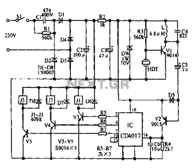
Fans can be controlled remotely with a switch that allows for speed adjustments, and this remote control can also be integrated with other household switches. Its primary feature is the use of a sub-transmission ultrasonic transmitter, which operates without...
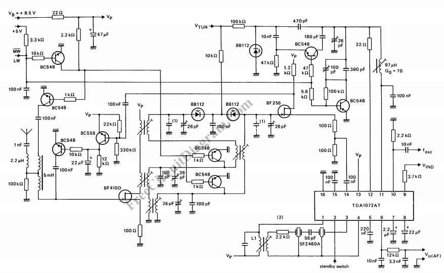
The TDA1072AT is a specialized integrated circuit designed for AM radio receivers, produced by Philips Semiconductors. This IC is intended for use in both mains-fed home receivers and car radios. It features a voltage-controlled oscillator that delivers signals with...

The hobby circuit described utilizes a unique approach to generate approximately 12,000 volts with a current of about 5 µA. It employs two silicon-controlled rectifiers (SCRs) that form dual pulse generator circuits. These SCRs discharge a 0.047 µF capacitor...
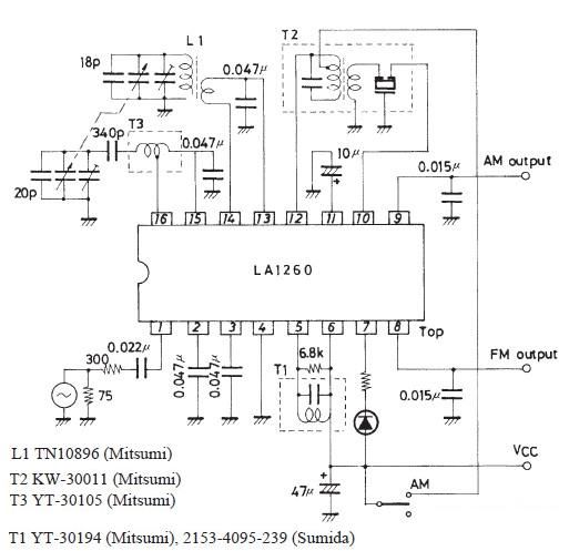
A very simple FM IF MW radio receiver circuit can be designed using the LA1260 IC manufactured by Sanyo Semiconductor. This FM IF MW radio receiver circuit schematic shows that the LA1260 IC can be utilized in AM and...
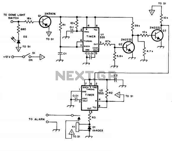
When this car alarm circuit is activated, it remains active for 80 seconds. There is a 15-second delay for the driver to enter and deactivate the alarm. All timings can be easily modified. The circuit utilizes two NE555 timers,...
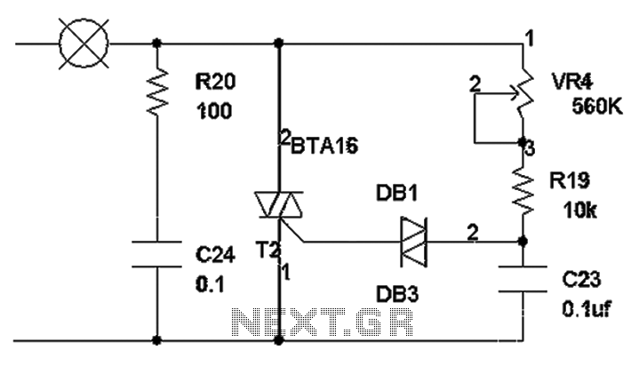
The TRIAC dimmer circuit diagram operates on the principle that a 220V lamp is controlled through the charging of capacitor C23 via resistors VR4 and R19. The charging time is influenced by the values of VR4 and R19, where...