
Worlds Smallest Stepper Motor with Arduino and EasyDriver

The project involves the design and implementation of a circuit to control a linear actuator, specifically utilizing a bipolar stepper motor extracted from a Blu-ray drive. The actuator is notably compact, making it suitable for applications requiring precise linear motion in limited spaces.
The circuit schematic includes essential components such as a microcontroller, which serves as the primary control unit. The microcontroller interfaces with the stepper motor driver, which is responsible for converting the control signals into appropriate current phases for the stepper motor. The driver typically utilizes H-bridge configurations to allow bidirectional control of the motor, enabling both extension and retraction of the actuator.
Power supply considerations are critical, as the stepper motor operates at specific voltage and current ratings. A regulated power supply circuit may be included to ensure the motor receives stable voltage levels during operation. Additionally, protective components such as diodes are incorporated to prevent back EMF from damaging the microcontroller or driver circuit.
Control logic can be implemented using pulse-width modulation (PWM) techniques to manage the speed and position of the actuator. The microcontroller can be programmed to interpret input commands, which may come from various sources such as a remote control, a computer interface, or sensors. This allows for sophisticated control schemes, including precise positioning and speed adjustments.
In summary, the schematic provides a comprehensive framework for connecting and controlling a linear actuator based on a bipolar stepper motor, emphasizing the integration of a microcontroller, motor driver, and power management components to achieve reliable and efficient operation.A video and the circuit with schematics for connecting and controlling the world`s smallest linear actuator based on a bipolar stepper motor from a Bluray drive. 🔗 External reference
Related Circuits
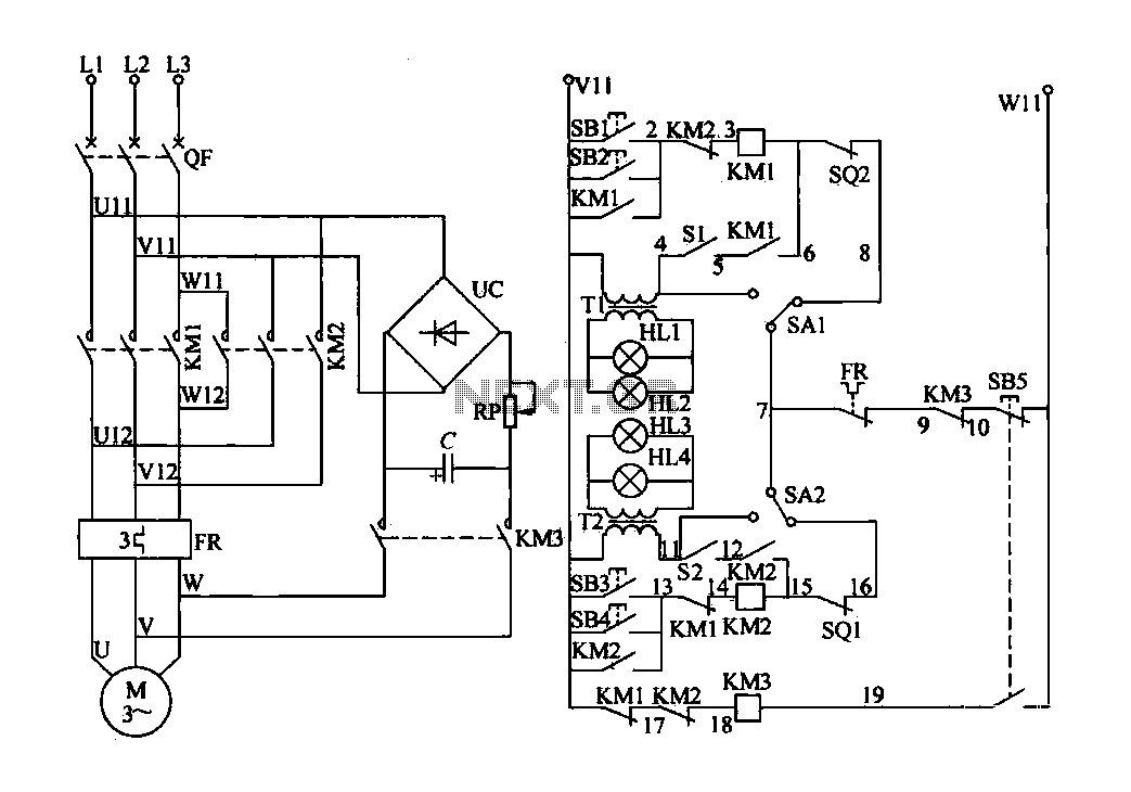
The electric valve control circuit consists of three main parts: the main lines, control lines, and power consumption brake line. The main circuit includes a power switch (QF), three-phase AC contactors (KM1, KM2), a thermal relay (FR), and a...

The schematic for controlling the motors is divided into three main sections, each serving a distinct function. The primary components featured in the schematic include the PIC 18F252 microcontroller, the SN754410 motor driver, and 2N2222 transistors. At the top...
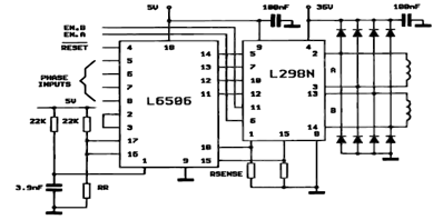
The following figure illustrates the control circuit for a two-phase bipolar stepper motor utilizing the current controller L6506. The L6506 integrated circuit generates the necessary signals to drive the inputs of the L298 bipolar stepper motor circuit driver. The circuit...
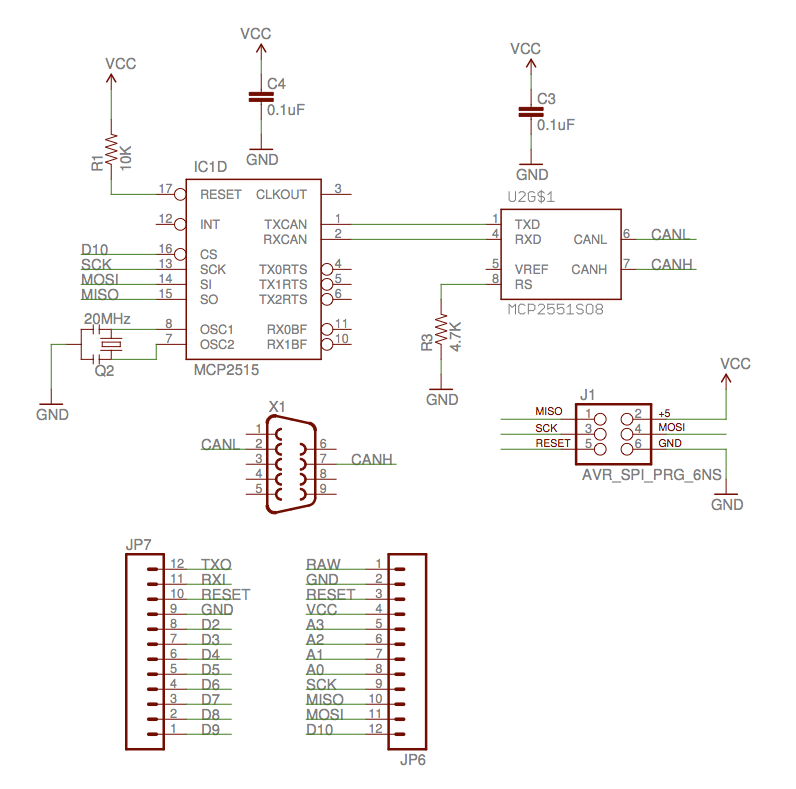
The implementation of the Controller Area Network (CAN) for aircraft applications is referred to as CAN-FIX, which is part of the MakerPlane Open Source Airplane project. This project aims to create an Arduino shield that facilitates communication over the...
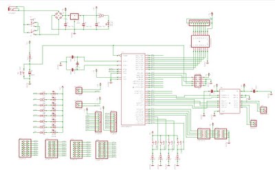
A microcontroller is used to control various types of DC motors, including permanent magnet DC motors, DC servo motors, and stepper motors. This project utilizes the AVR-008 microcontroller from Circuits-Home, which is frequently referred to as the 3-in-1 driver...
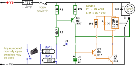
The schematic illustrates a Simple Motorcycle Alarm Circuit Diagram created by Ron J. It incorporates micro-switches to safeguard removable panels and... The Simple Motorcycle Alarm Circuit Diagram is designed to enhance the security of motorcycles by utilizing a series of...