
Two Phase Bipolar Stepper Motor Control

The circuit in question employs the L6506 current controller to manage the operation of a two-phase bipolar stepper motor. The L6506 is designed to provide precise current control, which is crucial for the efficient operation of stepper motors. This integrated circuit outputs the control signals that dictate the timing and magnitude of the current supplied to the motor phases, ensuring smooth and accurate stepping.
The L298 is a dual H-bridge motor driver capable of controlling the direction and speed of the stepper motor. It receives the control signals from the L6506, which are generated based on the desired stepping sequence and motor control parameters. The L298 is capable of driving the motor in both forward and reverse directions while providing the necessary current to each phase of the motor.
In this configuration, the L6506 monitors the current flowing through the motor coils and adjusts the PWM (Pulse Width Modulation) signals sent to the L298 accordingly. This feedback mechanism allows for precise control over the motor's performance, reducing the risk of overheating and enhancing efficiency. The circuit typically includes additional components such as diodes for flyback protection and capacitors for stability, ensuring reliable operation in various conditions.
Overall, this driving circuit effectively combines the functionalities of the L6506 and L298 to deliver a robust solution for controlling two-phase bipolar stepper motors, suitable for applications requiring accurate positioning and smooth motion control.The following figure shown the driving of two phase bipolar stepper motor control circuit by using the current controller L6506. The IC L506 generates the needed signals to drive the inputs of the L298 of this bipolar stepper motor circuit driver
🔗 External reference
Related Circuits
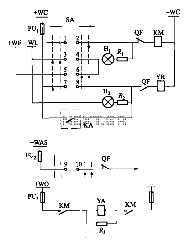
Factories and enterprises operating at voltages of 10 kV and below commonly utilize the CD10 (formerly CD2) type electromagnetic actuator as a circuit breaker. This mechanism features a mechanical anti-jump device. The control signal circuit for the CD10 actuator...
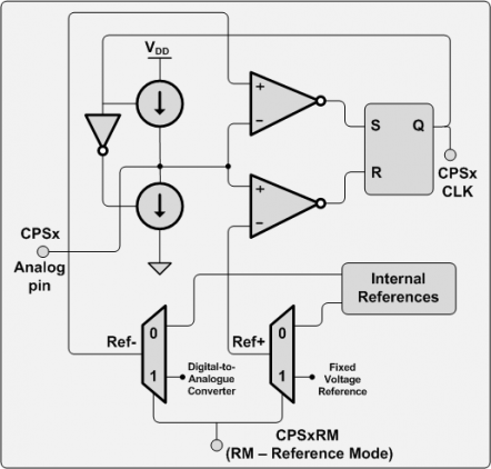
There are numerous applications for this hardware, including touch pads, proximity sensors, capacitive sensor readouts, high-precision capacitance measurements, ultra-small capacitance change detection, soil moisture sensing, and skin moisture measurement, among others. However, after searching for examples, it was surprising...
This controller is designed primarily for controlling model trains and can deliver approximately 12-15 Volts, though it operates effectively at voltages as low as 3V, including a 6V supply for certain accessories. The maximum output current is theoretically around...
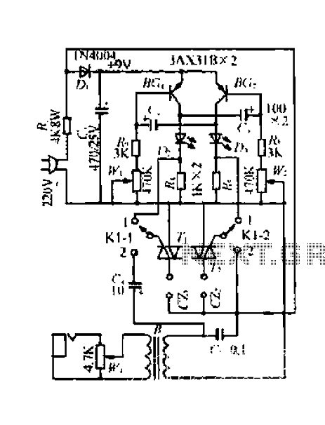
A 220V mains power supply is reduced using a control circuit designed by N. Guanidine D. Yi. The circuit features a spike Bode and provides a +9V voltage supply. It includes components such as a control port (G), a...
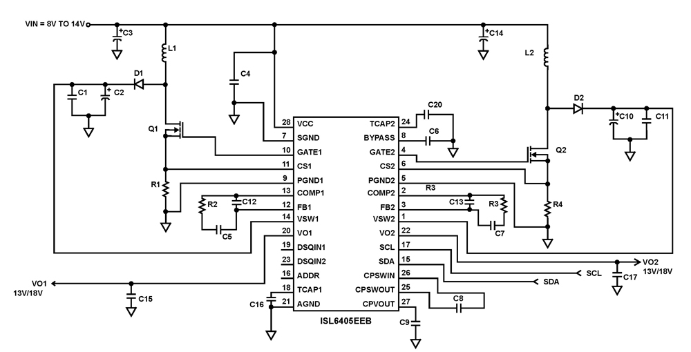
The ISL6405 is a highly integrated voltage regulator and interface integrated circuit (IC) designed to supply power and control signals from advanced satellite set-top box (STB) modules to the low noise blocks (LNBs) of two antenna ports. This device...
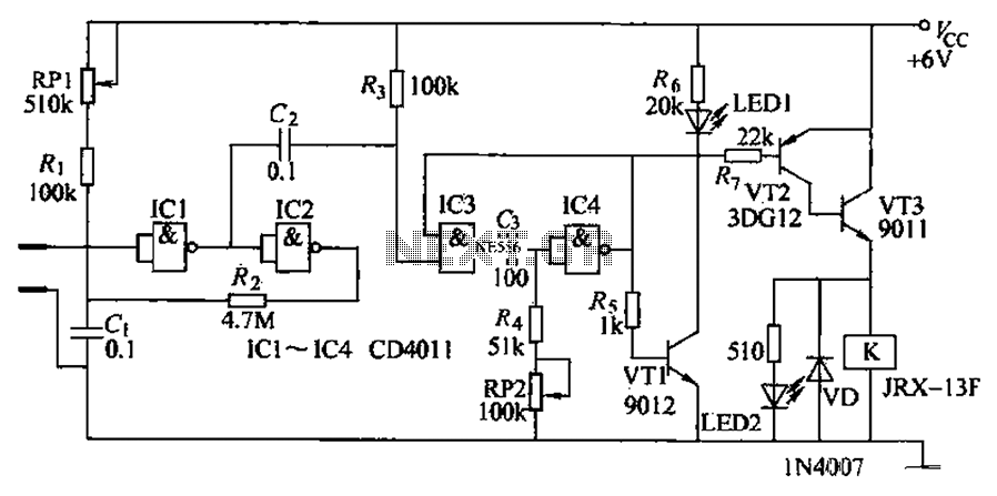
The automatic irrigation control circuit is designed to manage crop irrigation based on soil moisture levels. It is applicable in various agricultural settings, including state farms, orchards, vegetable greenhouses, and large farmland areas. The circuit comprises a soil moisture...