
a simple Astable Multivibrator with the help of a circuit diagram

The astable multivibrator circuit typically consists of two NPN transistors, two resistors (R1 and R2), and two capacitors (C1 and C2). The configuration allows for continuous switching between the two transistors, creating a square wave output. The resistors R1 and R2 are connected to the collector terminals of the transistors, providing biasing and stability to the circuit. The capacitors C1 and C2 are crucial in determining the frequency of oscillation, as they charge and discharge, controlling the timing of the switching action.
In practical applications, the frequency of oscillation can be calculated using the formula:
\[ f = \frac{1.44}{(R1 + R2) \cdot (C1 + C2)} \]
Where:
- \( f \) is the frequency of the output square wave,
- \( R1 \) and \( R2 \) are the resistances in ohms,
- \( C1 \) and \( C2 \) are the capacitances in farads.
Additionally, the duty cycle of the output waveform can be adjusted by varying the values of the resistors and capacitors, allowing for flexibility in design based on specific application requirements. The astable multivibrator is widely used in applications such as clock pulses, tone generation, and timer circuits due to its simplicity and effectiveness in generating a square wave output.An Astable Multivibrator is a switching circuit which switches its output on and off for a designed time period. This article also describes about its working. An Astable Multivibrator or a free running oscillator circuit is generally used to generate square waves for a specified time period.
The name Astable Multivibrator is used for it because, it does not have a stable state and it switches between two quasi stable states. Consider the instant at which the DC supply is switched on. Even though, both the transistors are made of the same material their is a chance for disproportion among the two and That is the key to the generation of vibrations. This phenomenon is further enhanced by the transistor configuration as shown in the figure. The collector terminal of T1 is connected to the base of T2 via a capacitor C1 and similarly the collector terminal of T2 is connected to the base of transistor T1.
So, due to this configuration only one transistor can remain switched-on at a time. The time period is determined by the capacitor connected to its base. As said above, at the time of providing supply to this circuit, any imbalance among the transistors can cause any one of the transistor to conduct more, let it be T1 now. As T1 turns on its collector potential will be VCEsat which is approximately equal to 0. 3v therefore the transistor T2 will get a base potential less than the cutin voltage 0. 7 and this prevents transistor T2 from turning on. Now since the capacitor C1 is connected in series with the base terminal of T2, the capacitor charges to vcc through RC1 resistor.
As the capacitor charges, the base voltage of T1 increases exponentially and when it is more than 0. 7 v, the T2 turns on. But the collector voltage of T2 drops to VCEsat which in turn is connected to the base of T1 and it drives T1 to switched-off state. Now C2 charges to vcc through Rc2 resistor and when the base voltage of T1 is more than 0. 7v T1 turns on and T2 goes off. This regenerative action continues until the power supply is maintained. Thus the time period depends on the value of C1 and C2 This circuit can function as as per our design.
But, there may be some small variation subsequently, because of the approximation provided in the values of capacitor and resistors. in fact we used only standard valued components available in market. 🔗 External reference
Related Circuits

Building a signal generator is an essential project for any analog DIY enthusiast. While already possessing a bench signal generator, the intention was to create a compact, battery-powered device for quickly testing new effect designs. An enclosure from a...
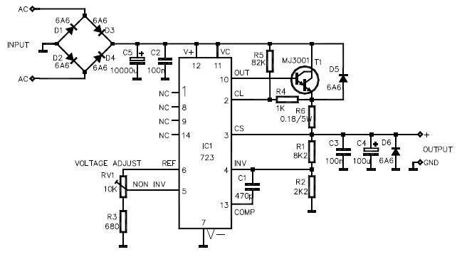
This LM723 variable power supply circuit design is a straightforward variable power supply capable of delivering an output voltage ranging from 8 to 30 volts, with a maximum output current of 3 amperes. The circuit features a low output...
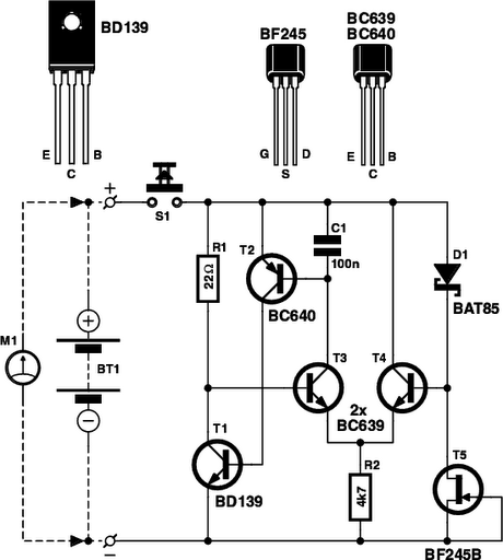
Is the battery empty, or is there something wrong with the device? This question can be challenging when a battery-powered device, such as a Walkman, appears to be non-functional upon switching it on. Before seeking professional servicing, the initial...
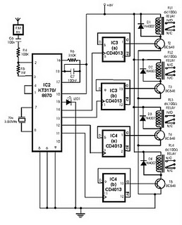
This project utilizes DTMF (dual-tone multi-frequency) signals, commonly used in telephones for dialing digits, as control codes. The DTMF tones are employed for frequency modulation of the carrier signal. At the receiver unit, these frequency-modulated signals are intercepted to...
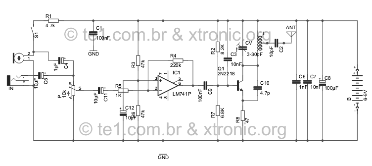
Evolution FM transmitter utilizing a 2N2218 transistor with an audio amplification stage using an LM741 operational amplifier. The design accommodates audio input from various sources such as MP3 players, MP4 devices, mobile phones, computers, and other audio sources, surpassing...
The above pictured schematic diagram is just a standard constant current model with a added current limiter, consisting of Q1, R1, and R4. The moment too much current is flowing biases Q1 and drops the output voltage. The output...