
Circuit FM transmitter for MP3 and MP4 Player 2n2218 and 741 opamp

The Evolution FM transmitter circuit is designed to efficiently transmit audio signals over FM frequencies, leveraging the 2N2218 transistor for amplification and the LM741 operational amplifier for audio signal processing. The circuit's architecture allows for the integration of multiple audio input sources, enhancing its versatility. The choice of a trimpot for signal level adjustment is particularly beneficial, as it offers the user control over the audio input, ensuring optimal sound quality and preventing distortion.
The coil design, featuring four turns of 22 AWG enameled wire, is critical for the transmitter's performance. The air core configuration minimizes losses and enhances the efficiency of the transmission. The specified diameter of 1 cm provides a good balance between size and inductance, which is essential for achieving the desired frequency response.
The connection of the antenna between the third and fourth turns of the coil is a strategic choice, as it helps in stabilizing the transmission signal, which is crucial for maintaining a clear audio output. The flexibility in antenna selection allows users to choose an appropriate antenna based on their specific needs and available materials, thereby increasing the accessibility of the project.
The inclusion of a P2 audio input jack broadens the circuit's application, making it compatible with a wide range of devices. The ability to disable the electret microphone through a switch adds an additional layer of functionality, allowing users to switch between different audio sources seamlessly. Overall, this FM transmitter design exemplifies a practical approach to audio transmission, combining simplicity with effective performance, making it an excellent project for both beginners and experienced electronics enthusiasts.Evolution FM transmitter with 2n2218 with audio amplification step using LM741 op amp with audio input for MP3, MP4, mobile, computer and other audio sources, beyond the traditional electret microphone. With great sensitivity to the input signal. Using fewer components and easy assembly makes it ideal for those who want even without much experienc
e assembling an FM transmitter with reasonable power. The coil should be obtained four winding turns of enameled wire 22 AWG air core self sustained and 1cm diameter. Also in this case we connect the antenna between the third and fourth loop because it ensures greater stability in the transmission.
The antenna can be a telescopic 80cm, a piece of stiff wire or a specific antenna for FM transmitter. Must be connected at the point marked by Ant and the coil is connected via C2. As the circuit has an audio input type P2 to be connected in many different audio source, we adopted a trimpot to adjust the signal level of the circuit.
Also adopted was a key to disable the electret microphone. 🔗 External reference
Related Circuits
Here are some circuit diagrams for driving relays from a microcontroller. Ensure the use of a 5-volt relay (this refers to the coil, not the load circuit) and verify that the relay has a sufficient rating for the load...
A distortion circuit is being developed utilizing a single 12AU7 tube configured as a diode. The design is acknowledged as basic, intended primarily for the purpose of adding distortion effects. The proposed circuit leverages the 12AU7 vacuum tube, which is...
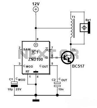
Zetex Semiconductors offers a siren driver integrated circuit (IC) known as the ZSD100, which is designed for use in alarm systems for vehicles and model crafts. By incorporating just a few additional components, as illustrated in the accompanying diagram,...
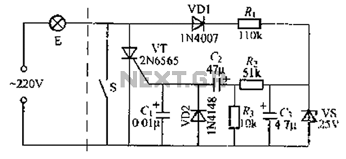
A delay circuit using an improved quenching lamp pull switch is described, focusing on its performance and the delay function in lighting control. The circuit exhibits a high degree of stability and reliability. When switch S is closed, the...
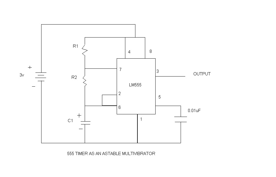
An astable multivibrator, commonly referred to as a free-running multivibrator, is a circuit that generates rectangular waves without the need for external triggering. The timing characteristics of this circuit are determined by the values of the resistors and capacitors...
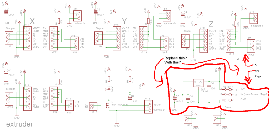
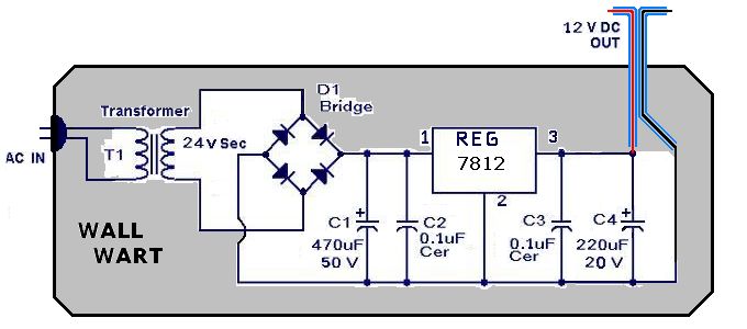
Preparing to assemble Adrian's Pololu stepper driver circuit has raised a question. He indicates that if using 5V from the Arduino Mega, the 78L05 voltage regulator should be omitted. This is a positive development, although there is an incorrect...