
radio remote control using dtmf circuit

The DTMF-based remote control system operates by generating specific tones that correspond to different commands for controlling electrical appliances. The DTMF generator circuit, centered around the UM91214B IC, is responsible for producing the necessary dual-tone signals. This IC is designed to output specific frequencies when certain pins are activated, allowing for the selection of various digits. The integration of a zener diode voltage regulator ensures that the IC receives a stable 3V supply, crucial for its proper functioning.
The FM transmitter circuit modulates the DTMF signals onto a carrier frequency, allowing the signals to be transmitted wirelessly. The receiver unit is equipped with a demodulator that captures the transmitted frequencies and converts them back into DTMF signals. These signals are then processed by the DTMF-to-BCD converter, which translates the tones into binary-coded decimal outputs. Each output corresponds to a specific appliance, enabling the user to control multiple devices from a distance.
The use of a 3.58 MHz quartz crystal provides the necessary timing accuracy for the DTMF generator, ensuring that the tones produced are within the required frequency specifications. The design is modular, allowing for easy adjustments and scalability, making it suitable for various applications in remote control systems. Proper layout and component selection are essential to minimize noise and interference, ensuring reliable operation in practical scenarios.Here we make use of DTMF (dual-tone multi frequency) signals (used in telephones to dial the digits) as the control codes. The DTMF tones are used for frequency modulation of the carrier. At the receiver unit, these frequency modulated signals are intercepted to obtain DTMF tones at the speaker terminals.
This DTMF signal is connected to a DTMF-to -BCD converter whose BCD output is used to switch-on and switch-off various electrical appliances (4 in this case) The remote control transmitter consists of DTMF generator and an FM transmitter circuit. For generating the DTMF frequencies, a dedicated IC UM91214B (which is used as a dialer IC in telephone instruments) is used here.
This IC requires 3 volts for its operation. This is provided by a simple zener diode voltage regulator which converts 9 volts into 3 volts for use by this IC. For its time base, it requires a quartz crystal of 3. 58 MHz which is easily available from electronic component shops. Pins 1 and 2 are used as chip select and DTMF mode select pins respectively. When the row and column pins (12 and 15) are shorted to each other, DTMF tones corresponding to digit 1 are output from its pin 7.
Similarly, pins 13, 16 and 17 are additionally required to dial digits 2, 4 and 8. Rest of the pins of this IC may be left as they are. . 🔗 External reference
Related Circuits
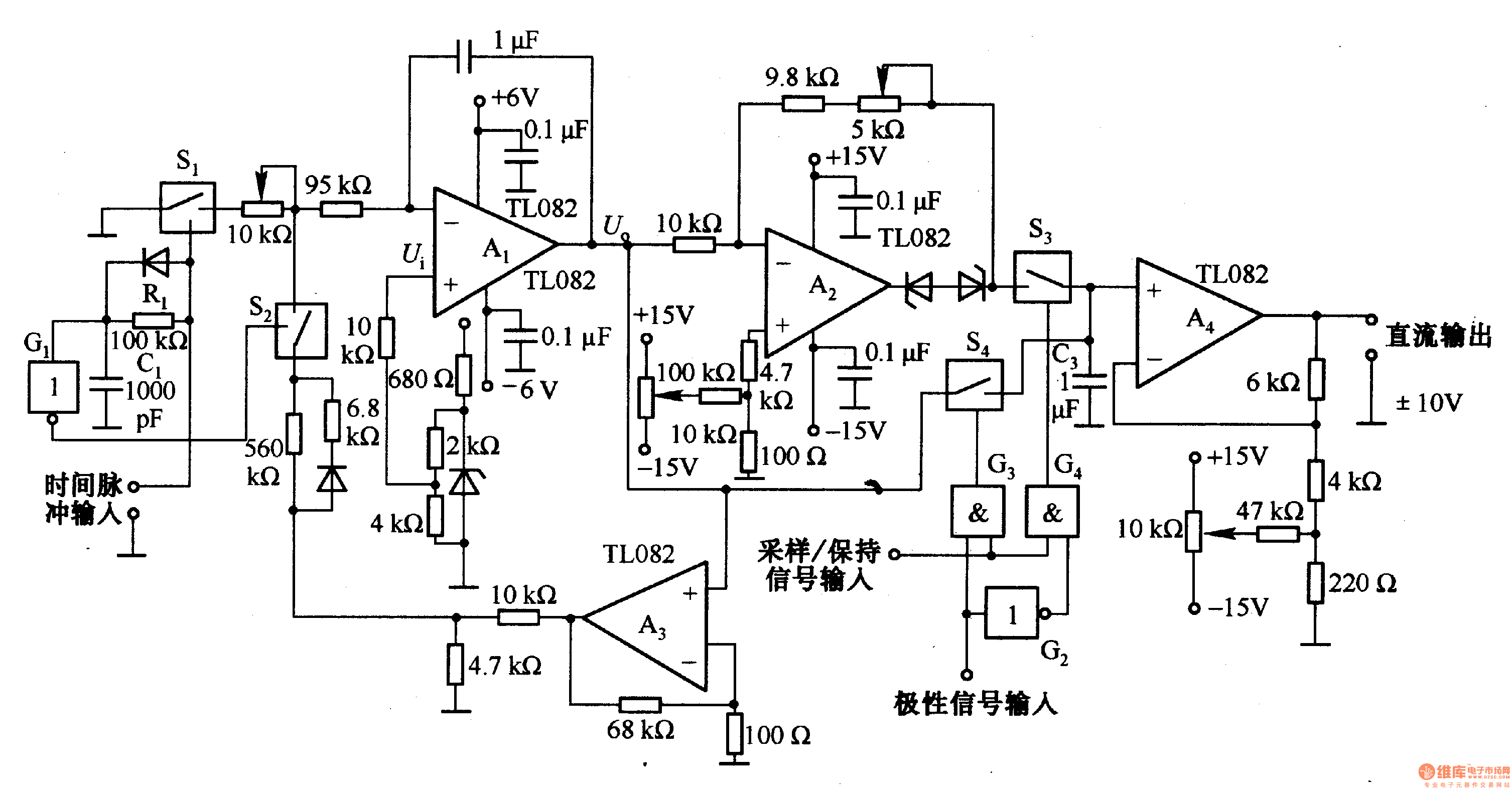
This circuit is designed for pulse width (time) to voltage conversion. According to the component parameters in the diagram, it can convert a pulse width of 0.1 seconds into an output voltage of 10V. When a conversion pulse is...
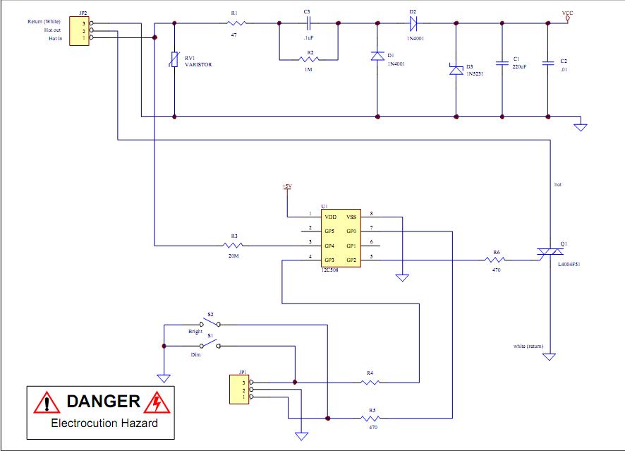
Assistance is required to modify a light dimmer circuit connected to a PIC12C508 microcontroller. This circuit is designed for the... The light dimmer circuit utilizing the PIC12C508 microcontroller serves to control the brightness of a light source through pulse width...
An innovative current detection method eliminates the power loss associated with the sense resistor in series with the motor. A 4-digit analog converter (DAC) facilitates digital control of the motor current path, simplifying the implementation of full, half, and...
This preamplifier was designed as a stand-alone portable unit, useful to control the signals generated by guitar pick-ups, particularly the contact "bug" types applied to acoustic instruments. Obviously it can be used with any type of instrument and pick-up....
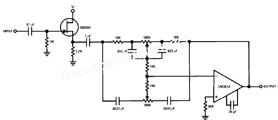
This circuit is a simple series tone control circuit utilizing the OP-Amp LM301A. The JFET 2N3684 provides high input impedance and low noise characteristics for the feedback buffer in the op-amp-based tone control. The tone control circuit described employs an...
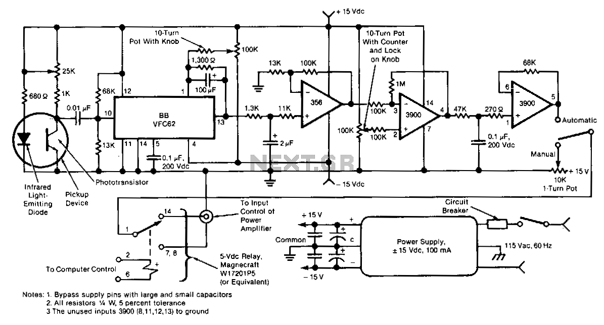
This electronic motor-speed control circuit is designed to operate in an electrically noisy environment. The circuit includes an optoelectronic pickup device, which is placed inside the motor housing to provide a speed feedback signal. The circuit automatically maintains the...