
color sensor circuit diagram

The color sensor circuit operates on the principle of light absorption and reflection. The three LDRs are sensitive to different wavelengths of light corresponding to the primary colors of red, green, and blue (RGB). Each LDR is paired with a specific colored filter that allows only its corresponding wavelength to pass through while blocking others. This selective filtering enables the circuit to determine the color of the object based on which LDRs are activated.
The output from the LDRs is fed into a logic circuit that interprets the signals. For instance, if only LDR1 (red) is activated, the output will indicate the presence of red. If both LDR1 and LDR2 (red and green) are activated, the output will indicate yellow, showcasing the circuit's ability to detect secondary colors. The logic circuit can be implemented using simple transistor-based gates or more complex microcontroller-based systems, depending on the project's requirements and complexity.
To ensure optimal performance, careful consideration must be given to the placement of the LDRs and lenses. The lenses should be aligned precisely to focus the incoming light onto the LDRs effectively. Additionally, the ambient light conditions should be controlled to prevent interference with the readings, as external light sources can affect the accuracy of color detection.
In summary, this color sensor circuit is a versatile tool for robotics and automation applications, allowing for precise color detection through a well-designed optical and electronic system. Proper assembly, calibration, and environmental control are essential for achieving reliable and accurate results in color sensing tasks.This is a color sensor Circuit Diagram. This circuit will sense 8 colors that are:, green, red and blue ; magenta, cyan and yellow ; and black and white. It`s will be very useful for robotics project. The object whose colour is required to be detected should be placed in front of the system. The light rays reflected from the object will fall on t he three convex lenses which are fixed in front of the three LDRs. The convex lenses are used to converge light rays. This helps to increase the sensitivity of LDRs. Blue, green and red glass plates (filters) are fixed in front of LDR1, LDR2 and LDR3 respectively. When reflected light rays from the object fall on the gadget, the coloured filter glass plates determine which of the LDRs would get triggered. When a primary coloured light ray falls on the system, the glass plate corresponding to that primary colour will allow that specific light to pass through.
But the other two glass plates will not allow any light to pass through. Thus only one LDR will get triggered and the gate output corresponding to that LDR will become logic 1 to indicate which colour it is. Similarly, when a secondary coloured light ray falls on the system, the two primary glass plates corres- ponding to the mixed color will allow that light to pass through while the remaining one will not allow any light ray to pass through it.
As a result two of the LDRs get triggered and the gate output corresponding to these will become logic 1 and indicate which color it is. When all the LDRs get triggered or remain untriggered, you will observe white and black light indications respectively.
Following points may be carefully noted : The LDR is mounded in a tube, behind a lens, and aimed at the object. The coloured glass filter should be fixed in front of the LDR as shown in the figure. Make three of that kind and fix them in a suitable case. Adjustments are critical and the gadget performance would depend upon its proper fabrication and use of correct filters as well as light conditions
🔗 External reference
Related Circuits
A transistor optocoupler interface circuit, as described in section 15.1.6, has been implemented. This circuit serves as a transistor interface with other circuits. The transistor optocoupler interface circuit utilizes a light-emitting diode (LED) and a phototransistor to achieve electrical isolation...
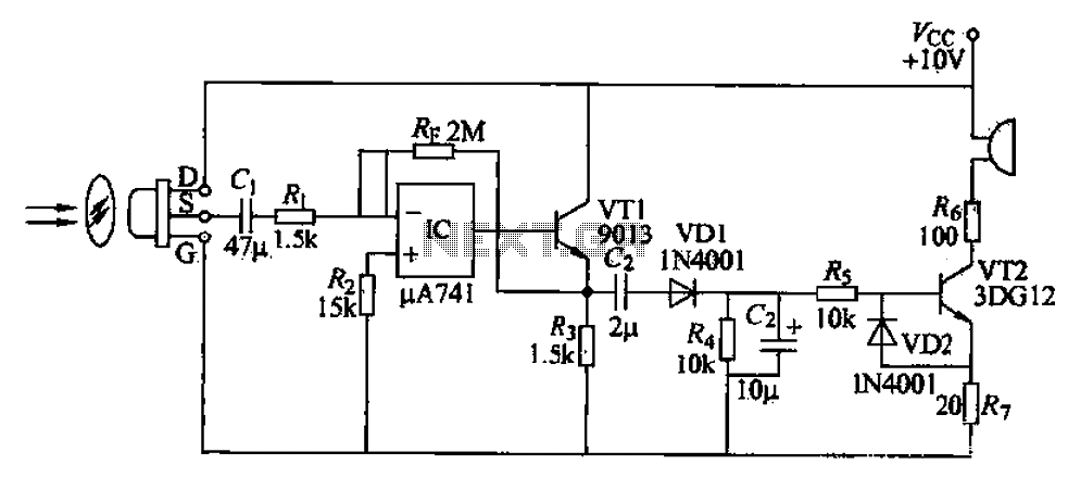
A simple burglar alarm circuit utilizes a pyroelectric sensor (IRA-E100SZI). When human movement is detected, it triggers an electric buzzer alarm. The sensor receives signals through an AC amplifier, which is then converted by a rectifier circuit into a...

Also known as a no-shot multivibrator, this circuit is often utilized as a pulse (square wave) signal source. The astable flip-flop functions as a strong positive feedback amplifier, with its two branches coupled by an RC timing circuit, resulting...
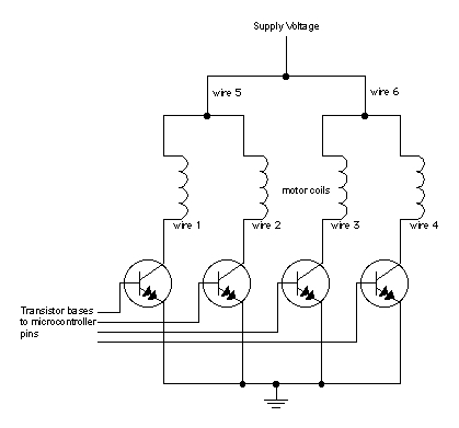
When moving objects with microcontrollers, three types of motors are particularly useful: DC motors, servomotors, and stepper motors. Most motors operate on the electrical principle of induction. When electric current flows through a wire, it generates a magnetic field...

This is a compact, easy-to-build amplifier that utilizes a single integrated circuit (IC) to deliver 40 watts of audio power. It is well-suited for amplifying audio signals from devices such as mobile CD players or iPods. The integrated circuit...

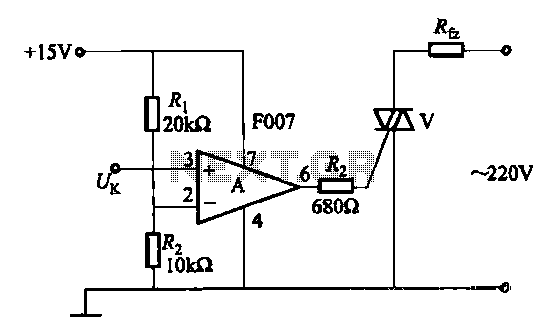
A 100W full-wave single-junction transistor trigger control circuit designed for constant or variable speed control of a wire feed motor. The input control signal consists of a voltage adjusted by the master potentiometer (RPs) and a feedback voltage from...