
digital wall clock with circuit diagram

No description available.
Related Circuits
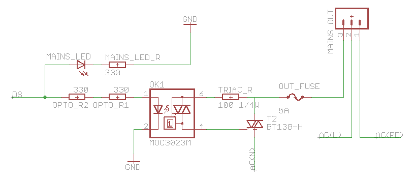
The heatsink on the triac is somewhat unclear. A maximum value of 10°C/W has been calculated, which raises concerns. The calculation is as follows: (maximum temperature - room temperature) / (maximum on-stage voltage * (milliamps / voltage) - junction-to-base...
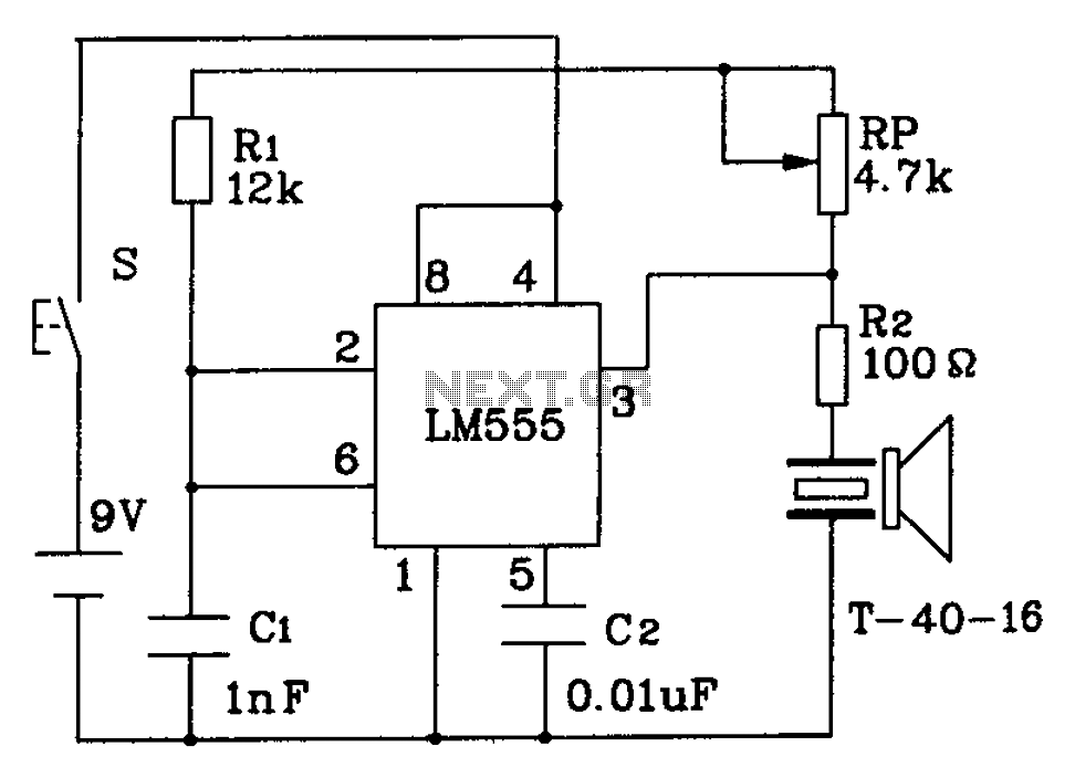
The circuit described is a 555 ultrasonic transmitter constructed to emit ultrasonic signals at a frequency of 40 kHz. It operates by generating oscillating pulse outputs from a 555 timer (specifically the T-40-16 model). The circuit is designed to...
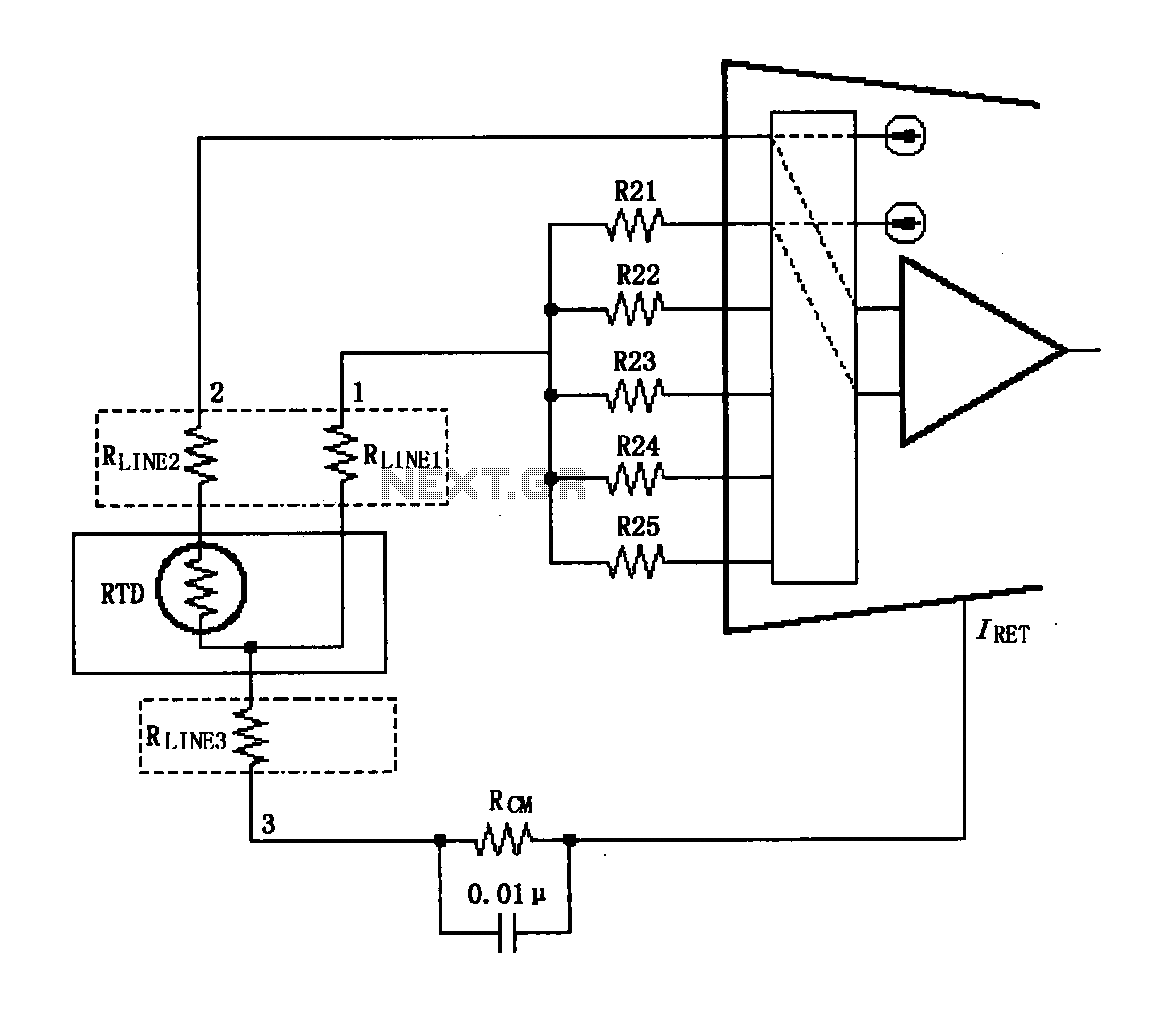
The circuit diagram illustrates the three-wire RTD connection for the XTR108. It is important to note that the lead resistance of the RTD sensor can introduce measurement errors. In the provided figure, connections "1" and "2" represent the lead...
This is a differentiator circuit. This circuit can be used to perform differential operations. There are two types of differentiators: the true differentiator and another type. A differentiator circuit is designed to output a voltage that is proportional to the...
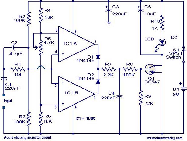
This circuit is designed to detect clipping in a specific waveform. Clipping occurs when the amplitude of a waveform decreases before reaching its expected limit. The circuit activates an LED as an indication that the tested signal is experiencing...
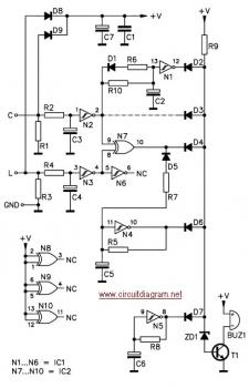
The circuit is designed to ensure that the headlights or side lights are automatically switched off after the ignition contact is turned off. This prevents the occurrence of a dead battery due to headlights being inadvertently left on. The circuit...