
electrometer schematics
The circuit operates based on the principles of electrostatics, utilizing a field-effect transistor (FET) as the main sensing element. The neon bulb, typically a low-voltage gas discharge lamp, ensures that the gate of the FET maintains a specified leakage current, essential for accurate readings. The configuration allows the FET to respond to electric fields by varying its conductivity, thus translating the electric field strength into a measurable current that drives the meter.
The sensitivity of the electrometer can be further enhanced by selecting a high-quality FET with low gate leakage and high transconductance. A careful selection of the adjustable resistor is also crucial; it allows for fine-tuning the circuit to accommodate various meter sensitivities. The circuit's design should minimize external influences, thus ensuring that the readings reflect only the electric fields of interest.
For optimal performance, the entire assembly should be housed in a non-conductive enclosure to prevent accidental grounding or interference from external electric fields. Additionally, it is advisable to include a calibration procedure using known charge sources to ensure the accuracy of the readings. The design can be further improved by incorporating shielding around the sensitive components to mitigate the effects of electromagnetic interference (EMI).
Overall, this electrometer design serves as an effective tool for detecting and measuring electric fields with notable sensitivity, making it suitable for educational demonstrations, research applications, and experiments involving electrostatics.The following circuit is an electronic approximation of the gold leaf electroscope`, except that this electrometer indicates polarity as well as electric field magnitude. It is incredibly sensitive! It will detect a television or an electrostatically charged comb from the other side of a room. It can even see` people moving about! The neon bulb se rves two purposes. It provides leakage at the FET gate and also helps to defend the FET against an electrostatic discharge. Do not omit the neon bulb the FET won`t get the proper biasing without it. Ideally, the neon bulb should be in darkness, though the circuit seems to work okay with the neon bulb illuminated.
The only effect is that the meter autozero` has a much shorter time constant when the neon bulb is illuminated. The meter can be of the VU` variety though meters in the range 100 A to 1 mA can be made to work. You may need to change the value of the adjustable resistor if a meter of widely different FSD to that specified is employed.
A source of small, cheap meter movements is those cheap battery testers their meters tend to be in the range 0. 5 mA to 1 mA. You won`t be able to walk around with this electrometer the needle will just kick between its end stops if you try.
Instead, it should be operated on a firm surface and left to settle for a minute or two. Adjustment of the METER CENTRE` adjustment is inevitably a trial and error affair, as bringing your hand near the electrometer will probably alter its reading. The probe can be just a few inches of wire. The impressive looking probe on my meter is nothing more than a redundant adapter from an emergency mobile phone battery!
I provided an earth connection through the body of the switch in anticipation that I might need to use my hand to remove excessive charge from the probe, but I haven`t actually needed to do that yet. 🔗 External reference
Related Circuits
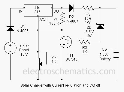
This is a solar charger circuit designed to charge Lead Acid or Ni-Cd batteries utilizing solar energy. The circuit captures solar energy to charge a 6-volt, 4.5 Ah rechargeable battery for various applications. It includes voltage and current regulation,...

The power supply is standard. The 110VAC input connects to connector N17, in series with a power switch SW1, a fuse F1, and the primary coil of transformer T1. The secondary coil of T1 generates 24VAC at 12 Amps,...
AC power is rectified and applied to the motor in one polarity when the momentary switch is held in one direction, and the polarity is reversed when the motor is held in the reverse direction. The remote car starter...

This document contains a collection of various useful and interesting electronic schematics. Some of these schematics are referenced or included in other documents on this site. Notably absent from this collection is extremely important safety information, which can be...

Protect your valuable laptop against theft using this miniature alarm generator. Fixed inside the laptop case, it will sound a loud alarm when someone tries to take the laptop. This highly sensitive circuit uses a homemade tilt switch to...

The circuit diagram illustrates a sound, light, and touch-controlled delay self-extinguishing switch. It comprises three main sections: the power circuit, the signal conversion detecting circuit, a delay circuit, and a control circuit. 1. Power Circuit: This section consists of...