This document contains a collection of various useful and interesting electronic schematics. Some of these schematics are referenced or included in other documents on this site. Notably absent from this collection is extremely important safety information, which can be found in the document titled "Safety Guidelines for High Voltage and/or Line Powered Equipment." Many of the circuits presented involve high voltage and/or direct line-connected high power systems, where improper handling could lead to severe electric shock. For high voltage equipment, additional safety information is available in the "Tesla Coils Safety Information" document. Laser power supplies and related schematics are detailed in the document "Lasers: Safety, Diode Lasers, Helium Neon Lasers, Drive, Info, Links, Parts." Information on electronic flash and strobe-related schematics can be found in "Notes on the Troubleshooting and Repair of Electronic Flash Units and Strobe Lights, Design Guidelines, Useful Circuits, and Schematics." Additionally, documents on troubleshooting consumer electronic equipment may contain information on isolation and variable transformers (Variacs), homemade degaussing coils, series light bulb adapters, and other useful test bench tools. General gadgetry and components can be salvaged from consumer electronics, as outlined in "Salvaging Interesting Gadgets, Components, and Subsystems." Schematics for testing capacitors, transistors, and other semiconductor devices, including a simple curve tracer design, can be found in the relevant documents. One basic circuit described is capable of supplying over 30 kilovolts from a low voltage DC source using a flyback transformer (LOPT) salvaged from a television or computer monitor. Typical output with a 12 VDC 2 A power supply or battery is approximately 12,000 V, with a current of around 1 to 2 mA at full voltage. Higher currents may be achievable, but the output voltage will decrease. For example, at 2 kV, currents exceeding 10 mA may be possible depending on the specific flyback transformer used. This circuit uses two 555 timers to provide variable frequency and variable pulse width drive to an inverter with a flyback transformer from a black and white or color TV or computer monitor. The input voltage can range from 5 to 24 V. Using a flyback from a MAC Plus computer with a removed faulty primary winding, an output exceeding 20 kV is possible (though caution is advised, as the flyback is likely not rated for more than 12 kV) from a 24 VDC, 2 A power supply. By adjusting the drive frequency and duty cycle, a wide range of output voltages and currents can be obtained depending on the load. With the addition of a high voltage filter capacitor (0.08 µF, 12 kV), this circuit can serve as a helium neon laser power supply operating on 8 to 15 VDC, depending on the required tube current and ballast resistor. The drive transformer, sourced from a black and white computer monitor (specifically a video display terminal), has a turns ratio of 4:1, wound on a nylon bobbin with a gapped ferrite double E core. The primary consists of 80 turns, while the secondary has 20 turns, both made with #30 wire. It is crucial to ensure the correct polarity; the base of the switching transistor should be activated when the driver is turned on. If the flyback includes an internal rectifier or if the goal is to achieve maximum output voltage of a specific polarity, the direction of drive is significant, as the largest pulse amplitude is generated when the switching transistor is active.This is a collection of various useful and interesting schematics. Some of these are also referenced by or included in other documents at this site. What isn`t here (this may not be everything): * Extremely important safety information. See the document: " Safety Guidelines for High Voltage and/or Line Powered Equipment ". Many of these circuits i nvolved high voltage and/or direct line-connected high power systems. Getting electrocuted could ruin your whole day. For really high voltage equipment, also see: Tesla Coils Safety Information. * Laser power supplies and other laser related schematics will be found in the document: "Lasers: Safety, Diode Lasers, Helium Neon Lasers, Drive, Info, Links, Parts". * Additional electronic flash and other strobe related schematics will be found in the document: " Notes on the Troubleshooting and Repair of Electronic Flash Units and Strobe Lights and Design Guidelines, Useful Circuits, and Schematics ".
* Isolation and variable transformers (Variacs), homemade degaussing coils, series light bulb adapter, and other Incredibly Handy Widgets(tm) for your test bench will be found in the document: "Troubleshooting and Repair of Consumer Electronic Equipment" and possibly in the specific document for each type of equipment. * General nifty gadget and other pack rat stuff can be found in the document: " Salvaging Interesting Gadgets, Components, and Subsystems " which identifies useful components which may be removed from common consumer electronics and appliances as well as unconventional uses for their subsystems, modules, or replacement parts.
* Schematics associated with the testing of capacitors, transistors and other semiconductor devices (includes simple curve tracer design), flyback transformers, etc. , will be found in the document dealing with each of these typse of devices. This basic circuit is capable of supplying up to 30 kilovolts or more from a low voltage DC source using a flyback (LOPT) transformer salvaged from a TV or computer monitor.
Typical output with a 12 VDC 2 A power supply or battery will be around 12, 000 V. Current at full voltage is typically around 1 to 2 mA. Higher currents are available but the output voltage will drop. At 2 KV, more than 10 mA may be possible depending on your particular flyback transformer. This is an ASCII file: F_hvinvert. html This circuit uses a pair of 555 timers to provide variable frequency variable pulse width drive to an inverter using a flyback transformer salvaged from a black and white or color TV or computer monitor. The input voltage can range from about 5 to 24 V. Using a flyback from a MAC Plus computer which had its bad primary winding excised, an output of more than 20 KV is possible (though risky since the flyback is probably not rated for more than about 12 KV) from a 24 VDC, 2 A power supply.
By adjusting the drive frequency and duty cycle, a wide range of output voltages and currents may be obtained depending on your load. With the addition of a high voltage filter capacitor (. 08 uF, 12 KV), this becomes a nice little helium neon laser power supply which operates on 8 to 15 VDC depending on required tube current and ballast resistor.
See the document: "Lasers: Safety, Drive, Info, Parts; Diode, HeNe, Ar/Kr Ion Lasers" for details. The drive transformer is from a B/W computer monitor (actually a video display terminal) and has a turns ratio of 4:1 wound on a 5/16" square by 3/8" long nylon bobbin on a gapped ferrite double E core. The primary has 80 turns and the secondary has 20 turns, both of #30 wire. Make sure you get the polarity correct: The base of the switching transistor should be driven when the driver turns on.
Where the flyback includes an internal rectifier and/or you are attempting to obtain the maximum output voltage of a specific polarity, the direction of drive matters as the largest pulse amplitude is generated when the switching transistor tur 🔗 External reference
Q1 and Q2 create an ALL-ON ALL-OFF circuit that, when in the off state, draws negligible current. P1 initiates the circuit, activating the relay and powering the two integrated circuits (ICs). The lamp is energized through the relay switch,...
This simple MOSFET power audio amplifier circuit, featuring a TL071C operational amplifier and two MOSFET power amplifiers, can deliver up to 45W at an 8-ohm load. The schematic is based on Siliconix applications and incorporates variations in voltage across...
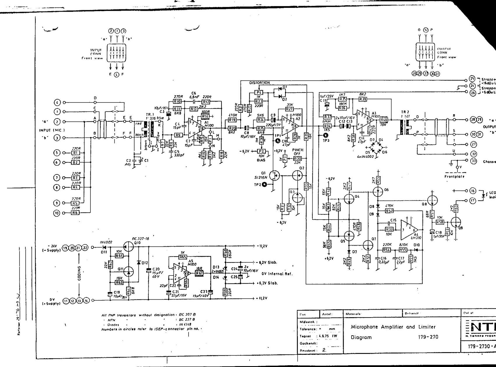
Here are some schematics and information that can be difficult to locate elsewhere. If there are schematics that should be included in this collection, please feel free to reach out. The intention is to expand this collection over time,...
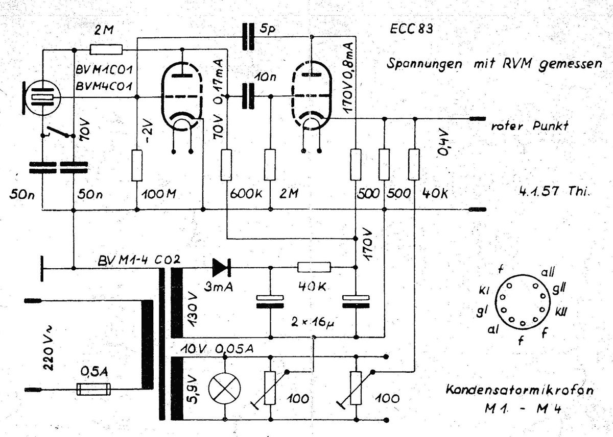
The power supply is integrated into the base of the microphone, which may cause hum issues, even with the onboard potentiometer designed to nullify this effect. Consequently, the microphone features two cables: one for power and another for audio...
This simple robot responds to light and avoids obstacles without the need for a microcontroller, programmer, or PC. The primary component in the circuit is a window discriminator, which functions as an advanced window comparator. Resistors R1 and R2,...
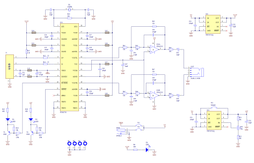
Creating a sound card is no longer a complex task. By utilizing the PCM2702 integrated circuit from Burr Brown / Texas Instruments, it is possible to design a fully functional USB sound card. This sound card can be powered...
We use cookies to enhance your experience, analyze traffic, and serve personalized ads.
By clicking "Accept", you agree to our use of cookies.
Learn more