
fm if mw radio receiver circuit using la1260 ic

The LA1260 IC is designed to facilitate the construction of efficient AM and FM radio receivers, making it an ideal choice for electronic hobbyists and professionals alike. Its high S/N ratio ensures clear audio reception, which is particularly beneficial in areas with weak signal strength. The built-in low-level AM oscillator with ALC enhances the receiver's ability to handle varying signal levels, ensuring consistent performance across different frequency bands.
The separation of components within the circuit is critical for maintaining performance integrity. The AM local oscillation coil and antenna circuit should be distanced from one another to reduce interference and optimize the receiver's sensitivity. The layout should be designed to minimize crosstalk between the AM oscillation injection pin and the RF input pin, as proximity can lead to signal degradation and affect overall performance.
The inclusion of an LED tuning indicator allows users to easily determine when the receiver is properly tuned to a station, enhancing usability. The independent output pins for FM and AM signals provide flexibility in circuit design, allowing users to connect to various audio processing units or amplifiers as needed.
In terms of power requirements, the specified operating voltage range of 3 to 8 volts DC provides versatility for different applications, enabling the circuit to be powered by various sources, including batteries or regulated power supplies. The recommended 4.5 volts DC serves as an optimal operating point, balancing performance and power consumption.
Overall, the LA1260-based FM IF MW radio receiver circuit presents a robust solution for radio reception, combining advanced features with practical design considerations to deliver a reliable and high-quality audio experience.As you can see in this FM IF MW radio receiver circuit schematic the LA1260 ic can be used in AM FM radio receiver electronic projects. LA1260 has integrated in the package many functions and features that are needed for radio receiver applications.
high S/N : FM 81dB, AM 53dB ;low-level AM oscillator with ALC MW 130mV SW 70 mV to 90 mV (7MHz) (2 4MHz) ;less AM whistle interference : whistle 1% at input 100dB/m. ;on-chip LED tuning indicator driver ;on-chip FM/AM selector; independent FM/AM output pins. The AM local oscillation parts, AM local oscillation coil, and antenna circuit parts such as bar antenna must be separated from each other as far as possible to prevent Qs from worsening. Pin 16 (AM oscillation injection pin) and pin 14 (RF input pin) must be separated from each other. The recommended power supply for this radio receiver circuit is 4. 5 volt DC, but the LA1260 ic accepts an input voltage range from 3 to 8 volts DC. 🔗 External reference
Related Circuits
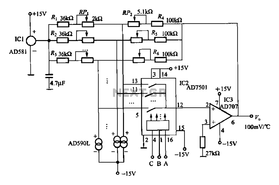
An 8-channel temperature detection circuit capable of monitoring eight different temperature sensors. The D581 serves as a 10.00V precision reference voltage source, providing a stable reference level for the detection circuit. Resistors RPi, RP2, and R4, along with the...
For a robot to perform its assigned tasks, a controller is necessary. This controller may be mechanical, electrical, electronic, or a combination of these. It acts as the brain of the entire system, providing the robot with its intelligence....
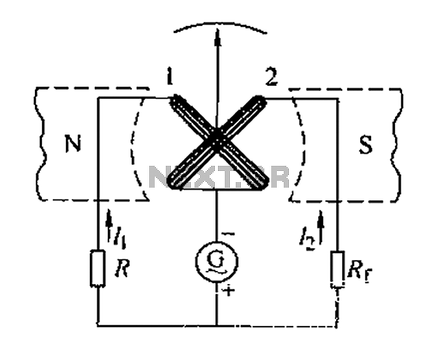
Also known as a megger insulation resistance meter, this device measures resistance at the megohm level. It is primarily used to assess the insulation resistance of motors, electrical circuits, and equipment. Additionally, it helps determine whether there is circuit...

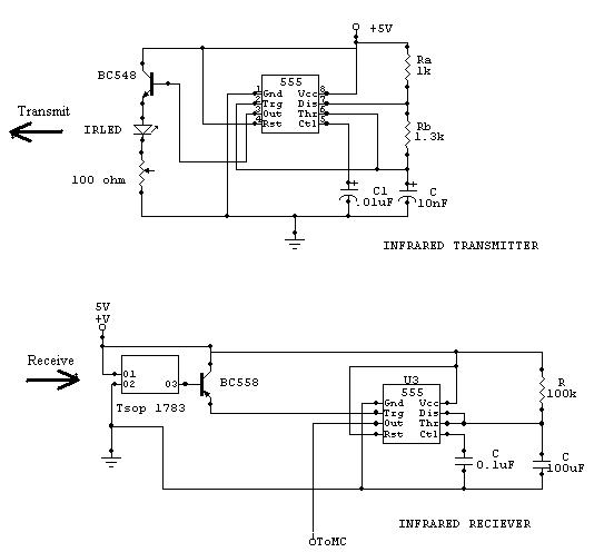
The input capacitor is used for low-frequency cut-off, with a standard value of 0.1 µF, resulting in a cut-off frequency of approximately 16 Hz. The input capacitor plays a critical role in electronic circuits, particularly in signal processing and audio...
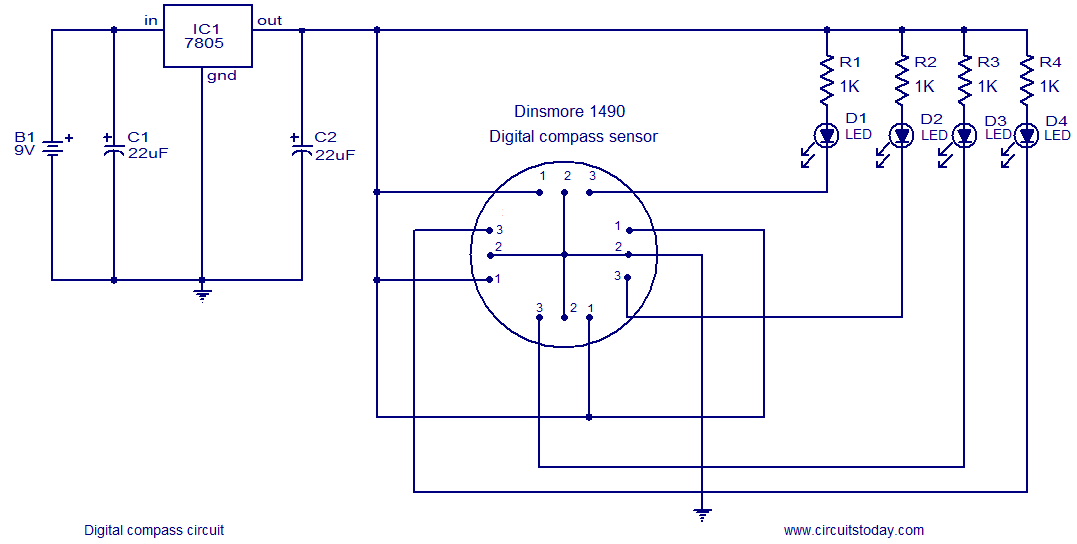
The following circuit illustrates a Digital Compass Circuit. This circuit is based on the 7805 IC. Features include a simple and accurate electronic compass. The Digital Compass Circuit utilizes the 7805 voltage regulator to provide a stable 5V supply necessary...
The main component is the LG26 one-inch screens integrated with the FSP107-2PS01 two-in-one electrical power package, which utilizes a direct drive CCFL modulator tube. This setup is compatible with screens from other manufacturers, such as Samsung and AU, but...