
Insulation resistance meter circuit

The insulation resistance meter operates by applying a high voltage to the insulation material and measuring the resulting current flow. The resistance is calculated using Ohm's law, where resistance (R) is equal to the voltage (V) applied divided by the current (I) measured. Typically, these meters can apply voltages ranging from 250V to 1000V, depending on the specific requirements of the insulation being tested.
The circuit design of an insulation resistance meter includes several critical components. A high-voltage DC source is employed to provide the necessary voltage for testing. This source is often coupled with a voltage regulator to ensure consistent output. The meter also incorporates a sensitive ammeter or microcontroller to measure the current that flows through the insulation material.
To enhance accuracy, the device may include a digital display that provides real-time readings of resistance values. Additionally, safety features such as overload protection circuits are integrated to prevent damage to the meter and ensure user safety during operation.
The schematic of an insulation resistance meter typically includes a high-voltage generator, a measurement circuit with an analog or digital readout, and safety mechanisms. The layout must be designed to handle high voltages safely, with adequate insulation and spacing between components to prevent arcing or short circuits.
In summary, the insulation resistance meter is an essential tool in electrical maintenance and safety, providing critical information about the condition of insulation in electrical systems. Its design and functionality are crucial for ensuring the reliability and safety of electrical installations.Also known as megger insulation resistance meter, the resistance in megohm level. Mainly used to measure the motor, the insulation resistance of electrical circuits, equipment, or judge whether the circuit leakage, insulation damage or short circuit. ~~ Insulation resistance meter is a major component of the magnetic and electric current ratio -/a as a measure of high voltage DC power hand-cranked generator. Insulation resistance shape table shown in Figure 5-2a. Insulation resistance meter circuit is shown
Related Circuits
A dimmer is a simple device used to reduce the brightness of incandescent lamps and to control the speed of collector motors. This concept has gained popularity due to the abundance of outdated Soviet circuits available on Lithuanian internet...
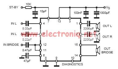
In practical applications, a series resistance must always be included. This component serves the dual purpose of limiting the current at pin 7 and smoothing the ON/OFF transitions during standby. In electronic circuits, particularly those involving integrated circuits (ICs) or...
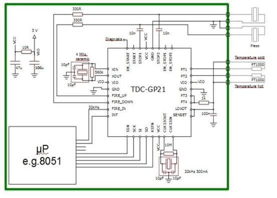
Enhancements include an analog front end, pin-to-pin compatibility for existing designs, an analog stabilized comparator, and simplified external circuit design. There is improved time and temperature measurement with reduced current consumption. The TDC-GP21 is ideally suited for designing compact...
This circuit is designed to control the mains pulse. The pulser's purpose is to switch the mains voltage on and off at intervals ranging from just under one second to a maximum of ten minutes. This functionality is beneficial...
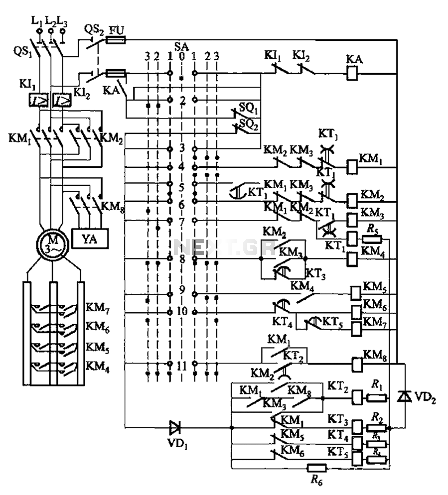
The system involves a master controller and a PQS1 Series Magnetic control panel, which includes a control circuit designed to manage the bridge crane hoist lifting mechanism. The master controller handle SA features seven positions: alongside the zero position,...
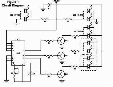
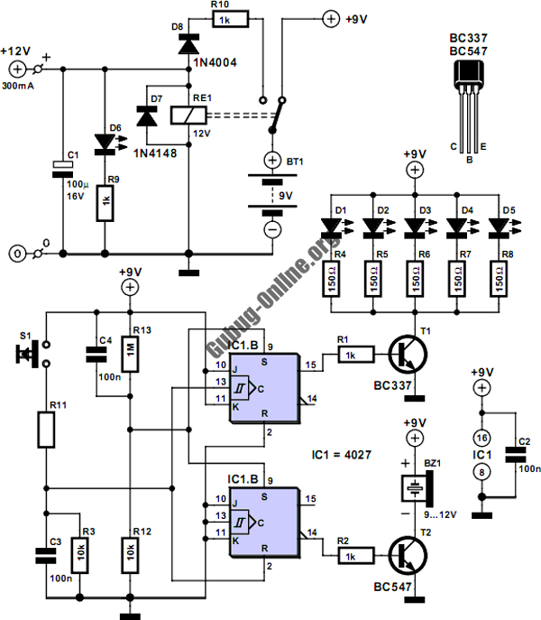
It consists of a 4047 low-power monostable/astable multivibrator, IC1, used in the astable mode to provide the timing pulses to control the flash rate of the LEDs. To accomplish the astable mode, pins 4, 5, 6, and 14 are...