
guild brian may box
The circuit design features a Cornish buffer, which serves to maintain signal integrity and drive capability, ensuring that the subsequent treble booster operates effectively. The buffer is typically implemented using a high-quality operational amplifier (op-amp) configured for unity gain, providing a low output impedance while preserving the tonal characteristics of the input signal.
The treble booster, associated with Brian May, is designed to amplify high-frequency signals, enhancing the brightness and clarity of the guitar tone. This stage may utilize discrete transistor configurations or specialized ICs optimized for high-frequency response. The interaction between the buffer and the treble booster is crucial, as the buffer allows for a consistent input impedance, which can affect the overall tonal response of the booster.
The layout of the circuit is essential for minimizing noise and interference. Careful routing of the input and output signals, along with proper grounding techniques, will help ensure that the circuit performs optimally. The SPDT switch configuration allows for seamless switching between the buffered and bypassed states, while the optional DPDT switch can facilitate an LED indicator to visually confirm the circuit's active state.
In summary, this circuit combines the benefits of a Cornish buffer with a Brian May treble booster, providing a unique tonal enhancement for guitarists seeking to achieve a distinctive sound. Proper implementation of the components and layout will result in a reliable and high-performance effect pedal.This is a bit of an unusual one because I`m not even sure what it is. It`s based on a schematic done by Analogguru and is obviously a Cornish buffer in front of a booster, so what I am assuming is that the Guild Brian May is the treble booster, and the whole circuit amounts to the modifications done by Pete Cornish when putting the effect in one o f his boards for Brian. Some or all of that may be wrong as it is just my assumption, so please correct me if anyone knows more, but the thought of a Cornish buffer into a Brian May treble booster seemed too good an opportunity to miss so I thought I`d have to do the layout! :o) The input socket should be taken directly to the board input and so only a SPDT stomp is needed for the switching because the buffer remains in circuit during bypass (the stomp is the "Sw#" connections shown in the layout).
You will of course need a DPDT stomp if you want to include an LED. For those wanting true bypass instead of the Cornish buffer. shame on you! :o) 🔗 External reference
Related Circuits
This is a first post expressing desperation. A used model #110-2079 gap bed 18-speed lathe with an American motor has been purchased, but there was a lack of realization regarding certain aspects. The model #110-2079 gap bed lathe is a...
This guitar effect circuit employs a straightforward high-gain amplification stage, succeeded by symmetric clipping achieved through a parallel diode clipper. The gain is provided by a 741 operational amplifier. The circuit design begins with a high-gain amplification stage utilizing the...
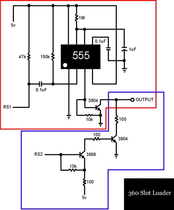
A slot-loading Xbox 360 features a mechanism similar to that of a MacBook, where a CD or DVD is inserted into a thin auto-loading slot rather than using a button to extend a mechanical tray. In contrast, the Xbox...
Both versions have the schematic attached. However, the resolution of the schematic is not very high. It is advisable to save the image above or download it to ensure accurate visibility of all details. There is no straightforward method...
This box is a set of nine relaxation oscillators. It blinks random patterns and looks cool. When the voltage on the capacitors charge to 65 volts, the neon gas ionizes and discharges the capacitors to 55 volts. The frequency...
The procedure outlines the construction of a Box, Lamp System, and Countdown System utilizing the AVR Mega8 microcontroller. The system features four blacklight lamps, each rated at 15W, which emit radiation primarily in the UVA spectrum, peaking around 350nm,...