
h bridge using mosfet transistor pwm
The H-Bridge circuit is designed to control a DC brushed motor by allowing bidirectional operation through the use of pulse-width modulation (PWM) for speed control. The configuration consists of two pairs of transistors, where each pair is responsible for switching the motor's connection to the power supply in opposite polarities.
In this setup, the inputs A and B are connected to the bases of the 2N3904 transistors, which act as signal amplifiers to drive the gates of the MOSFETs. The IRF7317 MOSFETs are used in the H-Bridge configuration to handle the high current and voltage required by the motor. The MOSFET IRF7905 is specifically designated for PWM control, allowing for efficient speed modulation of the motor.
The operation of the H-Bridge can be summarized as follows: when input A is high and input B is low, the motor will spin in one direction (e.g., clockwise). Conversely, when input A is low and input B is high, the motor will spin in the opposite direction (e.g., counterclockwise). The PWM signal, applied to the gate of the IRF7905 MOSFET, modulates the effective voltage supplied to the motor, thereby controlling its speed. The frequency of the PWM signal is set at 1kHz, which is suitable for many DC motors, providing a smooth operation without audible noise.
Protection diodes should be added across the MOSFETs to prevent back EMF generated by the motor from damaging the transistors and MOSFETs during switching. It is crucial to ensure that the selected components can handle the maximum current draw of 1.1A at the operating voltage of 6V. Proper heat dissipation techniques should also be considered for the MOSFETs to prevent thermal overload during operation.
This H-Bridge configuration is a versatile solution for controlling DC brushed motors in various applications, allowing for precise speed and direction control through simple input signals.Make H-Bridge for controlling DC brushed motor with PWM. One bridge will control 1 DC motor. Bridge will have 3 inputs: A, B and PWM. A and B will be direction control while one PWM signal will control motor speed no matter in which direction it will spin. Will this circuit work (of course ill have to add protection diodes but first i want to know if it will work with PWM) A and
B will select direction of motor and no matter if it will spin clockwise or counterclockwise same one PWM signal will set its speed. Transistors connected to A and B are 2n3904, P and N mosfets of bridge will be IRF7317 and mosfet with PWM will be IRF7905.
Motor voltage is 6V and maximum current draw is 1. 1A. PWM freq 1kHz 🔗 External reference
Related Circuits
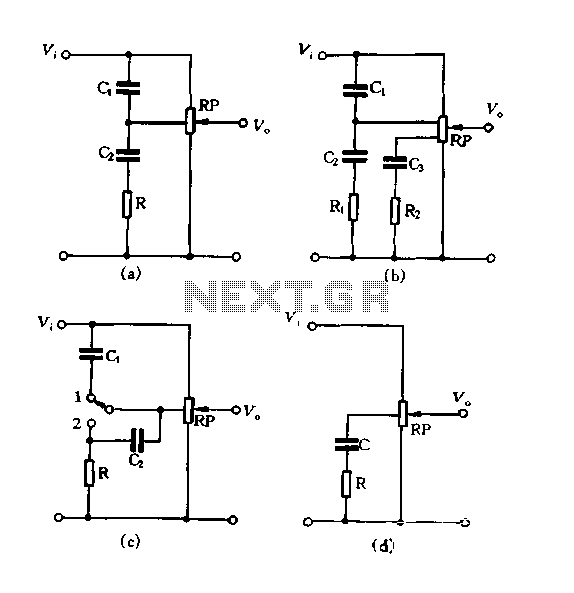
Figure 1.88 illustrates the loudness control circuit utilizing multiple taps on a potentiometer. In Figure (A), the connection is made between the tap and the potentiometer's input, along with the ground. An RC compensation network is employed, where the...
The reason why I am using an LCD display is because it allows me to display many characters and it doesn't need to be refreshed as 7-segment LED displays. Also, the interface requires less I/O pins. For this project,...
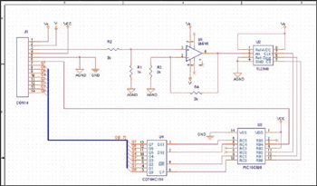
This example demonstrates the design of a circuit that incorporates both analog and digital components, features multiple power planes, and utilizes a single ground plane that is divided into analog and digital sections while maintaining a common reference point. The...
This article describes a 2-Input alarm developed on the PIC LICK-1 Module using a Microchip PIC16F628-04. The program uses the internal 4MHz oscillator and if any other frequency is used, the timer values will need to be changed. A...
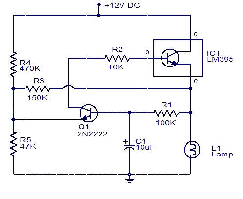
This circuit for a powerful flashing lamp is suitable for use in vehicles. The LM395 integrated circuit, also known as a super-transistor, is a highly robust monolithic power transistor that includes features such as thermal protection and current limiting....
If you have been following on Twitter, you might have seen a tweet about a "Transistor Clock" kit that allows for the construction of a wall clock using 194 discrete transistors and numerous other components. This kit has been...