
alarm using PIC16F628-04

The described 2-Input alarm system employs a Microchip PIC16F628-04 microcontroller, which operates efficiently with its internal 4MHz oscillator. The microcontroller is programmed to manage two detection zones, allowing for a versatile security solution that can be tailored to specific needs. The two zones are connected to the microcontroller via the I/O pins RA1 and RA2, which serve as inputs for the respective detection circuits.
Zone 1, connected to RA1, can be configured to monitor a smaller area, such as a tool storage space, while Zone 2, connected to RA2, can cover a larger area, such as a garage. The design allows the operator to selectively enable or disable Zone 2, providing flexibility in security management. This feature is particularly useful in environments where certain areas may not require constant monitoring, thus conserving resources and reducing false alarms.
The alarm system is designed to trigger an alert when a detection circuit is activated, which can be achieved through various types of sensors, such as motion detectors or door/window sensors. When a sensor within a zone is triggered, the corresponding input pin (RA1 or RA2) sends a signal to the microcontroller, which processes the input and executes the programmed response, such as sounding an alarm or sending a notification.
The design considerations include ensuring that the timer values are appropriately set based on the operating frequency of the microcontroller. If the internal oscillator frequency is altered, the timer settings must be recalibrated to maintain the correct timing for the alarm system's response. This aspect is crucial for the reliability of the system, as precise timing can directly affect the performance of the alarm.
In summary, the 2-Input alarm system developed on the PIC LICK-1 Module is a practical and flexible solution for security applications, allowing for tailored monitoring of different zones while providing the operator with control over the system's functionality. The use of the PIC16F628-04 microcontroller ensures efficient processing and responsiveness to security events.This article describes a 2-Input alarm developed on the PIC LICK-1 Module using a Microchip PIC16F628-04. The program uses the internal 4MHz oscillator and if any other frequency is used, the timer values will need to be changed.
A two zone alarm means the system has two separate detection circuits and can identify which circuit was triggered. The circuit uses lines RA1 and RA2 as zone 1 and zone 2. The operator can only enable or disable Zone 2. This allows situations such as disabling a large zone such as the garage, while an ultrasonic detector covering a smaller zone, such as toolboxes or equipment, remains enabled. A more practical application would be in a small store with a workroom at th 🔗 External reference
Related Circuits
When you use microcontrollers in your designs, sometimes you face a problem how to show user required data. Several LEDs, 7 segment display or LCD module can be solution. But if you must show a lot of information simultaneously,...

This is a radio transmitter circuit diagram designed for integration into radio collars using the NE 555 integrated circuit. The circuit transmits a pulse in the FM band, specifically between 88 MHz and 105 MHz. The radio transmitter circuit utilizes...
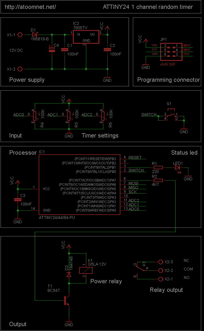
This random timer circuit is based on an Atmel ATTINY24 AVR driving one power relay. It can be used to switch on and off other circuits randomly. For instance, in a model railroad setup, this circuit can activate and...

This circuit diagram represents an indicator designed to display a battery voltage of 12 volts. The working principle involves comparing the battery voltage with a reference voltage using the LM324 integrated circuit, which is a low-power quad operational amplifier....

This room light controller project automatically uses a microcontroller to manage a visitor counter, providing a reliable circuit for controlling the room lighting. The room light controller circuit integrates a microcontroller that processes inputs from a visitor counter. This setup...
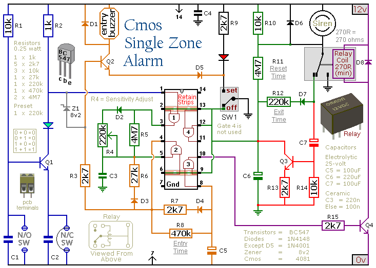
This circuit includes automatic exit and entry delays, a timed bell cut-off, and a system reset feature. It is designed to support both normally-open and normally-closed switches and can accommodate standard input devices such as pressure mats, magnetic reed...