
MIXED ANALOG/DIGITAL DESIGN USING SPLIT POWER GROUND PLANES

The circuit design outlined involves a hybrid approach, integrating both analog and digital circuitry to leverage the advantages of each domain. The separation of the ground plane into distinct analog and digital sections is critical in minimizing noise interference, which is often a challenge in mixed-signal designs. This separation allows for a cleaner signal integrity in the analog section while providing the necessary power and signal integrity for the digital components.
In this schematic, multiple power planes are employed to ensure that each section of the circuit receives appropriate voltage levels while managing power distribution efficiently. The analog section typically operates at lower voltages and requires careful consideration of power supply decoupling to prevent noise from the digital section from affecting sensitive analog signals. Capacitors and inductors may be strategically placed near power pins of the analog components to filter out high-frequency noise.
The digital section, on the other hand, may utilize higher voltage levels and faster switching speeds. It is essential to design the power planes with adequate trace widths to handle the current requirements of the digital components without significant voltage drop. Additionally, proper layout techniques, such as using short traces and minimizing loop areas, should be employed to reduce electromagnetic interference (EMI).
The common reference point between the analog and digital sections is crucial for maintaining signal integrity. This point should be strategically located to minimize ground loops and ensure that both sections can operate effectively without introducing noise into the system. Careful attention should be given to the return paths of the signals to ensure they do not cross between the analog and digital grounds, which could lead to crosstalk and signal degradation.
Overall, the design of a circuit with mixed analog and digital components requires a thorough understanding of both domains and careful planning to ensure that the performance of the circuit meets the desired specifications while minimizing potential issues related to noise and power integrity.This example shows how to design a circuit with a mixture of analog and digital parts, multiple power planes, and a single Ground plane split into analog and digital sections that have a common reference point.. 🔗 External reference
Related Circuits
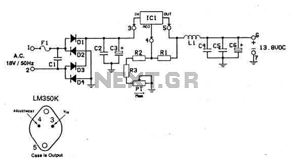
This power supply is designed for use with RF equipment such as linear amplifiers, transmitters, receivers, and any application that requires a clean and noise-free signal. The circuit is straightforward and can be powered using a 220V/18V/3A transformer connected...
The AquaCont is an electronic system which permits to manage and to monitor most of the parameters of all the electric devices that can be found in an aquarium. The PIC18F4520 used to realize it combines a real-time clock...
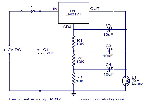
This document describes a lamp flasher circuit utilizing the adjustable voltage regulator IC LM317T. The LM317 can supply a maximum current of 1A, making it suitable for use with lamps up to 12W. This type of circuit has significant...
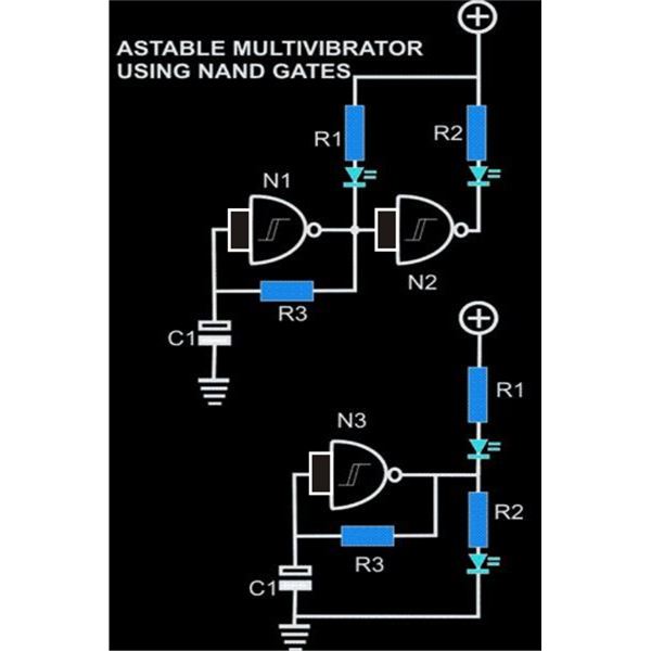
An astable multivibrator is an electronic configuration that generates continuous alternating high and low pulses from two outputs operating in tandem. The IC 4093 consists of four individual NAND gates in one package, specifically Schmitt trigger types, which provide...
This project provides a straightforward scientific calculator utilizing an AVR microcontroller. It features two keypads as illustrated in the circuit diagram, and the results are displayed accordingly. The scientific calculator circuit based on an AVR microcontroller is designed to perform...
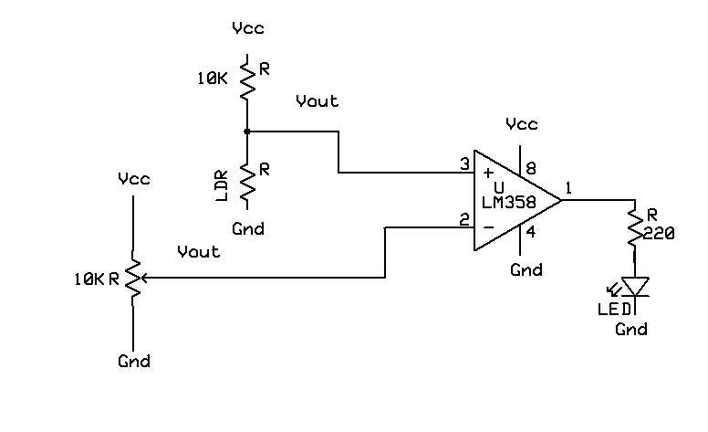
A light-based sensor utilizing an LDR (Light Dependent Resistor) and an operational amplifier (Op Amp). This circuit can be employed for applications such as line followers. The operation of the Op Amp is foundational to this design. It features...