
input output instructions 8051 assembly language

The 8051 microcontroller architecture is designed to facilitate a variety of applications through its versatile pin configuration. Each of the four ports (P0, P1, P2, P3) can be utilized for both input and output, allowing for efficient data handling in embedded systems. The ability to address entire ports simplifies programming, enabling the manipulation of multiple pins simultaneously.
In practical scenarios, the initialization of pins is crucial for proper operation. For instance, when configuring a port for input, setting all pins to logic HIGH can be efficiently achieved by loading a single hexadecimal value (FF) into the port register. This method not only saves programming time but also ensures that all pins are uniformly set, reducing the likelihood of errors during input operations.
The reset functionality is particularly important in embedded applications, as it allows for the reinitialization of the microcontroller without the need for physical intervention. This feature is essential for applications requiring reliability and stability, such as industrial automation or consumer electronics.
The choice of crystal frequency directly influences the performance of the microcontroller, with a range of 3 to 24 MHz allowing for flexibility in application design. Higher frequencies can lead to faster processing times, which is beneficial for time-sensitive tasks.
When interfacing with external components, such as sensors or actuators, careful attention must be paid to the electrical characteristics of the pins being used. For instance, the inclusion of pull-up resistors, as noted for the AT89S51, is a common practice to ensure stable input readings, particularly when dealing with open-collector outputs.
Overall, this comprehensive understanding of the 8051 microcontroller's architecture, pin configurations, and programming techniques lays a solid foundation for developing sophisticated embedded systems. The tutorial serves as a stepping stone for users to explore and implement their unique projects, leveraging the capabilities of the 8051 family of microcontrollers.This tutorial is in continuation with previous tutorials on 8051 Assembly Programming. Now we will learn how to give input and output instructions to 8051 microcontroller(s) using assembly programming language. The microcontroller has total forty pins in all. Most of the pins of 8051 microcontroller have more than one function. The first function is the input /output operation and the second function can be some special function like they can be used as counters or for serial communication. In microcontroller there are four ports (collection of pins) P0, P1, P2 &P3. These ports have 8 pins each as shown. As we will see later on we will be able to address the whole port during programming. Whenever we are talking about 8051 we are talking of the family of microcontrollers having the architecture of 8051.
They are all same except for some additional features, pins distribution and packaging. VCC and GND: - The pin 40 is Vcc i. e. it is given 5V and pin 20 is GND i. e. it is given 0V (supplied from power source) for powering up the microcontroller. CONNECTING THE CRYSTAL (XTAL1- XTAL2): The pin numbers 18 - 19 are used to connect the crystal. The frequency of this crystal determines the machine cycle. With 8051 family we can use a crystal having frequency from 3 to 24 MHz. RESET PIN CONNECTION (RST): The reset pin i. e. pin number 9 is used to reset the program just like we restart a computer, the program starts executing from the very beginning. When reset is used the program counter is set back to zero and the values in all other registers are lost.
EA/VPP: The EA pin no. 31 is known as external access. The 8051 microcontrollers have on chip ROM so the EA/VPP is set to one (or Vcc). In case there is no on- chip ROM, like in case of 8031 we set this pin equal to zero. This pin cannot be left unconnected. This is the basic setup of microcontroller that you need to have in order to perform an 8051 activity. The pins ALE/ PROG, EA/ VPP and PSEN may have some modifications. We will discuss this wherever it is necessary. This is a module that has been prepared by us. You can see that a 40 pin base has been mounted on the PCB (printed circuit board) instead of directly soldering the microcontroller to PCB which maybe damaged while soldering.
Here a microcontroller AT89S52 has been shown which is a member of 8051 family. The above circuit is valid for all the members of 8051 family except the AT89S51. In AT89S51, we also have to add pull up resistor at port zero for Input/ Output. (Check the data sheet of AT89S51 microcontroller for the same) So far we have discussed the basic setup required for initializing the microcontroller and now comes the interesting part i. e. how to program 8051 using assembly language i. e. carry out input/output operations. All the ports of 8051 can be used for Input or Output. Let`s get started. Some illustrations are listed below showing how to access the different pins and ports. Remember for receiving input the input pins or port must be initialized to logic HIGH i. e. 1 and in the subsequent example complete port has been used for receiving input. So rather than assigning logic high to each pin, FF hex value i. e. binary 11111111 is loaded to the input port. Sometimes we may only need to observe a single bit and perform an action based upon it like: receiving an input of temperature alarm and if the signal goes high (i.
e. temperature is above a certain limit) the buzzer goes off. Now you are ready for the real thing. We will start with a simple activity to give you a feel and also you can use this tutorial to implement your own ideas. For this you will need a typical parallel programmer or an ISP (In system programmer). The ISP is generally cheaper and you don`t need to remove the µController from the circuit to burn it.
The burners/programmers will cost you around Rs 1500-2500. Do try to buy a USB burner/programmer as parallel ports are n 🔗 External reference
Related Circuits
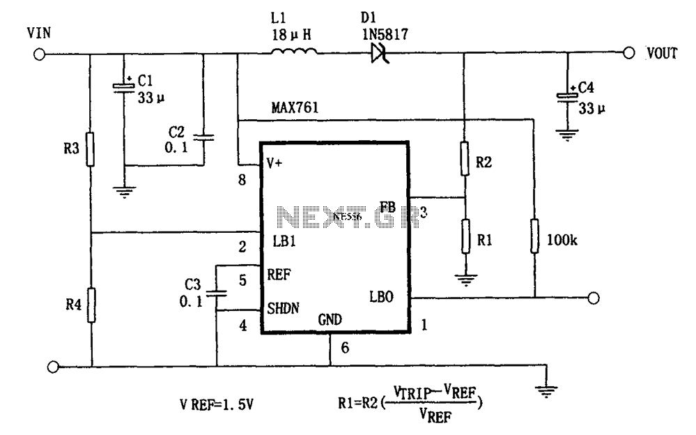
The circuit features an efficient, low-power output voltage boost DC-DC converter, MAX761, along with a few external components that facilitate adjustable power conversion. The output voltage is determined by the ratio of resistors R1 and R2, calculated using the...
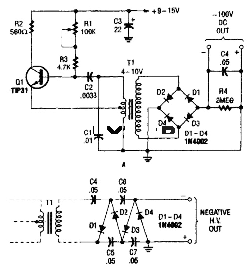
The combination of a Hartley oscillator and a step-up transformer can generate significant negative high voltage, particularly when the voltage output of the transformer is multiplied by the circuit in B. The Hartley oscillator is a type of LC oscillator...
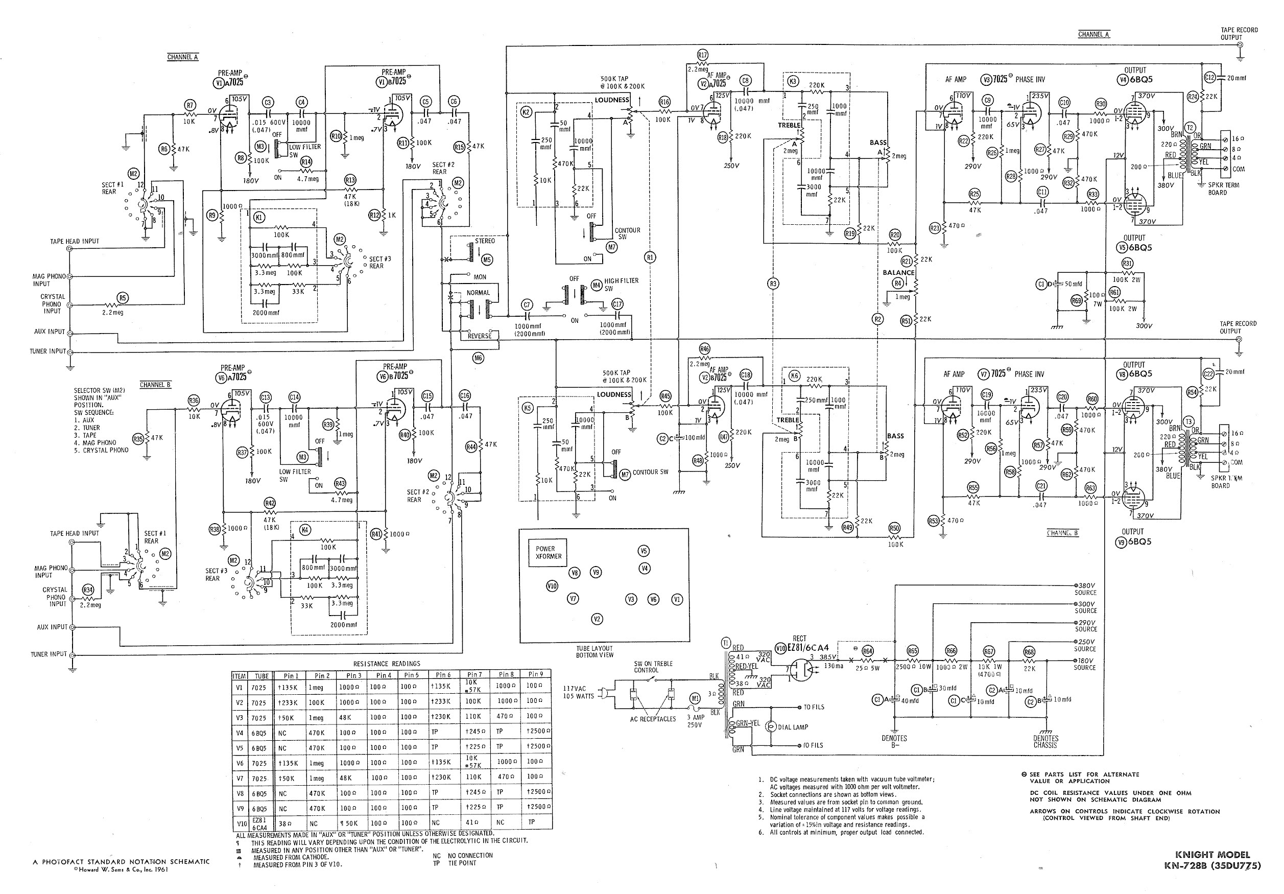
Ty - Concerning the updated schematic of the AF/PI stage, it appears that resistor R45 is not present. Additionally, the disk capacitor bypassing R44 is marked as 68nF750 with a tolerance of 10%, which is presumed to be the...
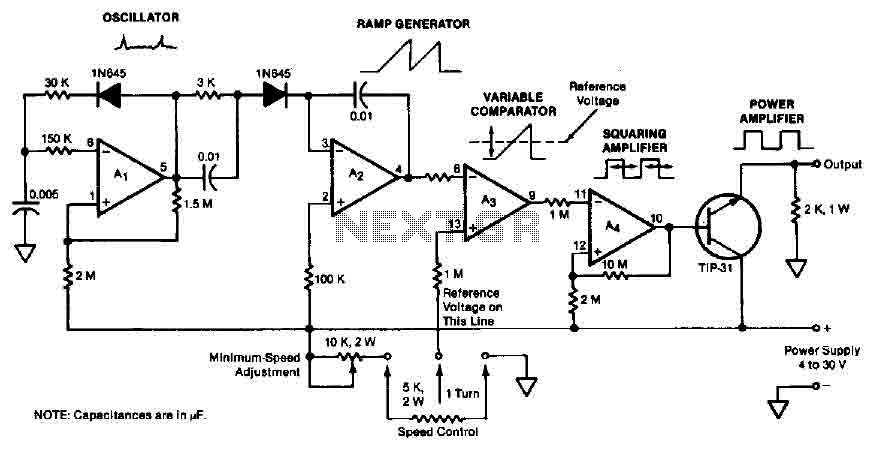
The quad operational amplifier circuit provides a pulse width modulation control ranging from 0 to 100 percent. The controller utilizes an LM3900 and operates with a single supply voltage between 4 to 30 V. A 1 kHz oscillator amplifier,...
The objective of this lab is to create a decimal counter that counts from 0 to 99 using the 80X51 microcontroller. A C program must be written for this purpose, which will then be compiled using the C51 compiler...
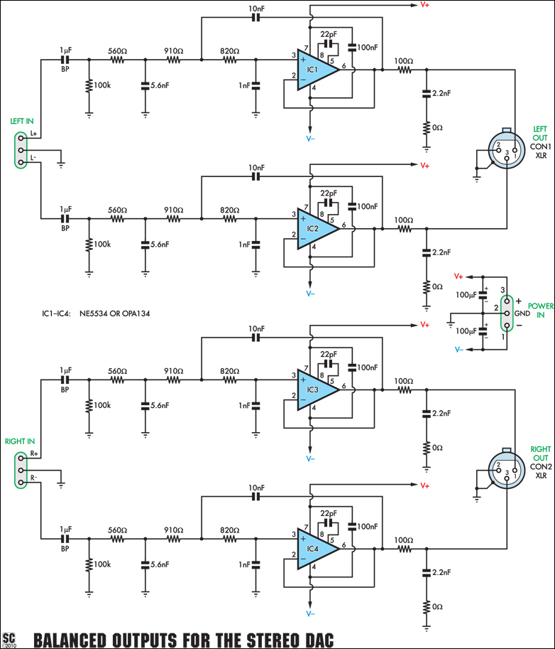
This add-on board is designed to provide a pair of balanced audio outputs for the High-Quality Stereo DAC (Digital to Analog Converter). Two 3-pin male XLR connectors are used for the new outputs, which can either replace or augment...