
Input pulse width controller circuit

The described quad operational amplifier circuit serves as an efficient pulse width modulation controller, leveraging the LM3900 operational amplifier to achieve precise control of motor speed or other applications requiring variable power delivery. The single supply voltage range of 4 to 30 V allows for versatile integration across various electronic systems. The core of the circuit is the 1 kHz oscillator amplifier, which serves to generate a stable frequency for the pulse width modulation.
The Az ramp generator plays a crucial role in producing a linear voltage ramp, which is essential for generating the desired pulse width. By applying this ramp signal to the inverting input of comparator A3, the circuit can effectively compare the ramp voltage with the control voltage. The comparator's output produces a pulse train whose width is modulated in accordance with the control voltage. This feature enables the circuit to adapt to different operational requirements, such as varying motor speeds based on external conditions or user input.
The adjustable potentiometer or external feedback source can be integrated into the circuit to provide dynamic control over the pulse width. This adaptability allows for real-time adjustments, making the circuit suitable for applications such as motor speed control in automotive systems or other machinery where speed regulation is critical.
The amplifier stage A4, with its gain of 10, functions as a pulse squaring circuit, ensuring that the output pulse train is sharp and well-defined, which is vital for driving the subsequent TIP-31 transistor. This medium-power transistor acts as a power amplifier, capable of handling significant current loads while providing efficient power delivery to the motor or other connected loads. The overall design of the circuit emphasizes reliability and performance, making it a valuable component in various electronic control systems.The quad operational amplifier circuit yields full 0 to 100 percent pulse width control. The controller uses an LM3900 requires only a single supply voltage of 4-30 V. The pulse repetition frequency is set by a 1 kHz oscillator amplifier that integrates AI. The oscillator feeds the Az ramp generator, which generates a linear ramp voltage for each pulse oscillator. The ramp signal feeds the inverting input of comparator A3, the control voltage feeds speed non-inverting input.
Thus, the output of the comparator is a 1 kHz pulse train, pulse width that changes linearly with control voltage. The control voltage may be provided by a _ adjustable potentiometer or an external source of feedback as an engine speed detection circuit. Depending on the setting of control voltage, the pulse duration can be set at a value between zero (zero average dc voltage applied to the motor) to full repetition period of pulses (voltage applied to the motor equal to voltage DC power supply).
An amplifier stage (A4) with a gain of 10 acts as a pulse squaring circuit. TIP-31 medium-power transistor is driven by the A4 and serves as a distinct stage of power amplifier.
Related Circuits
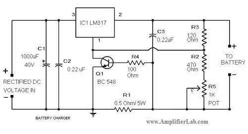
The circuit diagram of a lead-acid battery charger is presented here. The main component of this circuit is the IC LM317. The lead-acid battery charger circuit utilizing the LM317 voltage regulator is designed to efficiently charge lead-acid batteries while providing...
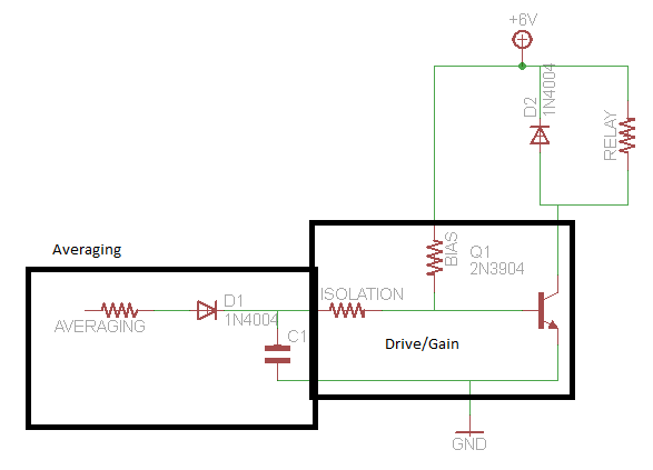
A circuit that activates a relay upon detecting audio pulses from one channel of an MP3 player. The intention is to synchronize recorded audio pulses with music to control a motor for mouth movement. For a stereo player, music...
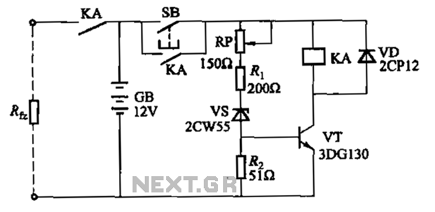
Deep discharge of a battery can lead to plate curing, which shortens the battery's lifespan. To prevent this, a discharge protection device can be implemented. The circuit diagram illustrates this mechanism. When the battery voltage falls to a predetermined...
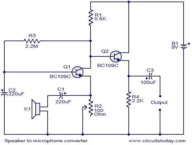
This circuit provides a straightforward method for converting a loudspeaker into a microphone. When sound waves impact the diaphragm of the speaker, fluctuations occur in the coil, generating a small induced voltage that is typically low in magnitude and...
This circuit is a compact +5V power supply that is beneficial for digital electronics experimentation. Inexpensive wall transformers with variable output voltage can be found at electronics shops and supermarkets. While these transformers are readily available, their voltage regulation...
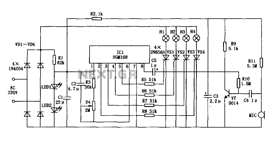
Family karaoke lighting design incorporates various methods for circuit control. The control circuit described here features a four-way light output with loop jumping and speed control capabilities. A microphone detects the acoustic signal strength, allowing the lights to jump...