
ir sensor

The infrared proximity switch is a simple yet effective circuit designed to detect the presence of nearby objects without physical contact. The core components of this circuit typically include an infrared LED, a photodiode or phototransistor, and a resistor. The infrared LED emits light, which reflects off nearby objects and is detected by the photodiode or phototransistor. When an object comes within a specified distance, the reflected IR light causes a change in the output of the photodetector, which can then be used to trigger other electronic components or systems, such as motors or alarms.
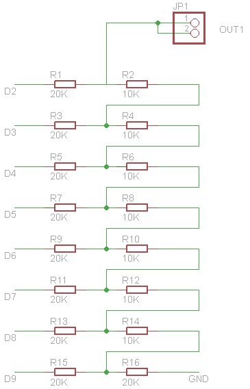
In the schematic, the infrared LED is connected to a power supply through a current-limiting resistor to prevent excessive current flow, which could damage the LED. The photodetector is connected in such a way that it can sense the reflected light. A potentiometer may also be included to adjust the sensitivity of the sensor, allowing for fine-tuning based on the application requirements.
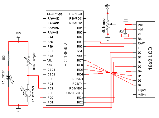
The output of the photodetector can be connected to a microcontroller or a simple transistor switch that can control larger loads, such as motors in a robotic system. This setup allows the IR proximity switch to serve as an effective "eye" for robots, enabling them to navigate their environment by detecting obstacles.
Overall, the design and functionality of the infrared proximity switch make it a valuable component in various applications, including robotics, automation, and security systems. The ease of construction and the availability of components further enhance its appeal for hobbyists and professionals alike.This section gives step-by-step instructions along with photos to the construction of IR Proximity Switch. Because this is a very simple circuit, only a schematic for the sensor is shown here: (For the PDF format click here.
) This tutorial`s objective was to help others built a infrared proximity switch. Complete construction details and photos ar e included in this tutorial for the sensor. Once the concepts were conveyed the reader could build an IR switch which could be connected to a robot and be used as the robot`s eyes. 🔗 External reference
Related Circuits

The AD592 is a two-terminal monolithic integrated circuit temperature transducer that produces an output current proportional to absolute temperature. It functions as a high-impedance temperature-dependent current source of 1 µA/K across a wide range of supply voltages. Enhanced design...
Scopeclock is a user-friendly hardware device designed to enhance the functionality of X-Y capable analog oscilloscopes. This hardware allows for the conversion of an analog oscilloscope into a scope clock. The project was developed by a team at CEDT...
The figure illustrates a multiple output crystal oscillator, which primarily consists of three gates of Al, four resistors, two capacitors, and a crystal. Resistors R1 to R4 offset two inverters within the linear range and are connected between pin...
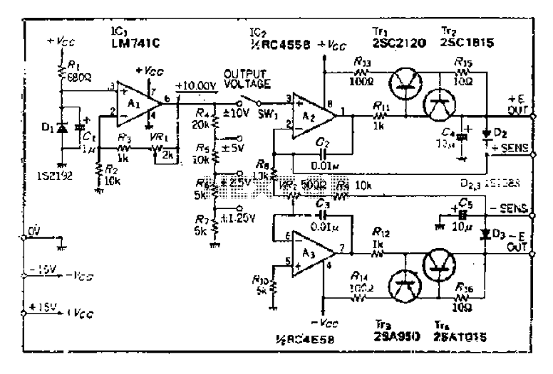
The maximum input voltage is 10V. An operational amplifier (op-amp) is used to provide a reference voltage of 10V, with its stability primarily determined by the characteristics of a temperature-compensated Zener diode (IS2192). The Zener voltage (Vz) can be...

This is a water sensor circuit design based on a Conductive Liquid Level Sensor. This single-chip circuit is compact and simple. It is an AC-excited fluid level sensor, which uses alternating current to provide biasing for the sensor probe,...
The circuit for the Digital Tachometer/RPM Counter consists of only a few devices. Wire them up according to the following circuit diagram. The PIC used is on a demonstration board, which means the clock, power, and ground pins are...