
Mutiple Output Crystal Oscillator Sensor

The multiple output crystal oscillator operates by utilizing the fundamental properties of the crystal to stabilize the frequency of oscillation. The three gates of Al (likely referring to a type of amplifier or inverter) serve as the core components that generate the oscillatory output. The crystal, acting as a frequency-determining element, ensures that the oscillator produces a stable and precise output frequency, which is critical in various applications such as clock generation, signal processing, and frequency synthesis.
Resistors R1 through R4 play a vital role in setting the operating point of the inverters, ensuring that they function within their linear range. This configuration is crucial for maintaining the stability and reliability of the oscillation. The feedback loop established by connecting the crystal between the specified pins allows for the necessary phase shift and gain required for sustained oscillation. The two capacitors in the circuit may be used for coupling or decoupling purposes, contributing to the overall performance and stability of the oscillator.
In summary, this multiple output crystal oscillator design effectively combines the elements of feedback, frequency stabilization, and gain control to produce reliable oscillatory signals suitable for a variety of electronic applications.As shown in the figure is a multiple output crystal oscillator. It is mainly composed of 3 gates of Al, four resistances, two capacitances and a piece of crystal. R1 ~ R4 offset two inverters within the linear range, and they are connected between foot 4 and foot 1 of A1 by crystal SJT to provide the feedback loop. It will produce oscillation only on th.. 🔗 External reference
Related Circuits
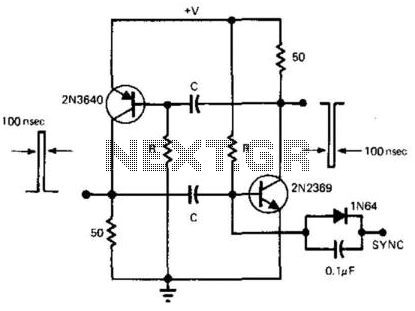
This simple and symmetrical free-running generator has a 50-ohm output impedance, a pulse width of 100 ns, and complementary outputs that swing from ground to the power supply voltage. It operates within a power supply range of less than...
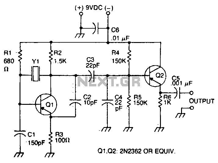
The oscillator transistor is Q1, and the crystal is placed between the collector and base. Feedback is improved by the use of the collector-emitter capacitor C2. Transistor Q2 is used as an output buffer. The circuit described features an oscillator...
A PLL oscillator, or phase-locked loop oscillator, is a control method that compares a controlled system or plant to a reference signal. A phase-locked loop (PLL) oscillator is a sophisticated electronic circuit designed to synchronize an output signal's phase and...
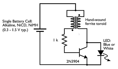
A transformer with two input leads and three output leads was used. An LED was connected to two of the output leads, and when a dead AA battery was connected to the input leads, the LED blinked for a...
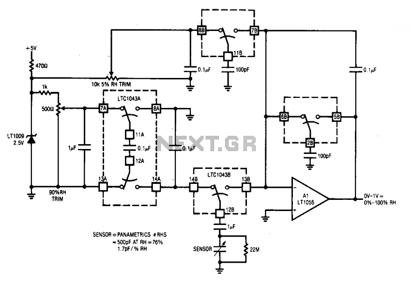
This circuit integrates two LTC1043 devices with a humidity transducer based on a charge-pump configuration. The specified sensor has a nominal capacitance of 400 pF at a relative humidity (RH) of 76%, exhibiting a slope of 1.7 pF/% RH....
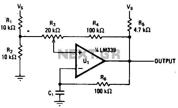
Varying the amount of hysteresis in this comparator circuit allows for smooth adjustment of output frequencies within the range of 740 Hz to 2 kHz. The hysteresis level, in combination with the time constant formed by resistor R6 and...