
lights led circuits schematics

The described circuit effectively monitors the flow of individuals in and out of a designated space, utilizing a straightforward yet efficient design. The arrangement of the LDRs allows for accurate detection of movement, as the sequential triggering of each sensor provides a reliable indication of entry or exit. The bicolor LED serves as a visual indicator of the room's occupancy status, enhancing user awareness.
The counters, based on the CD4017 IC, are configured to increment or decrement based on the signals received from the LDRs. This counter configuration ensures that the total number of persons in the room can be tracked accurately, providing real-time feedback on occupancy levels. The logic ICs that follow are tasked with processing the counts from both counters, enabling the system to determine if the room is occupied or vacant.
To mitigate the effects of ambient light on the LDRs, it is advisable to implement shielding or to utilize enclosures that limit light exposure. This can significantly enhance the reliability of the circuit in various lighting conditions. Alternatively, the integration of infrared sensor modules can provide a more robust solution, as they are less susceptible to environmental light variations and can offer improved detection capabilities.
Overall, this circuit design presents a practical solution for monitoring room occupancy, with flexibility in component selection and implementation strategies to suit specific application needs.The circuit uses two LDRs which are placed one after another (separated by a distance of say half a metre) so that they may separately sense a person going into the room or coming out of the room. Outputs of the two LDR sensors, after processing, are used in conjunction with a bicolour LED in such a fashion that when a person gets into the room it
emits green light and when a person goes out of the room it emits red light, and vice versa. These outputs are simultaneously applied to two counters. One of the counters will count as +1, +2, +3 etc when persons are getting into the room and the other will count as -1, -2, -3 etc when persons are getting out of the room. These counters make use of Johnson decade counter CD4017 ICs. The next stage comprises two logic ICs which can combine the outputs of the two counters and determine if there is any person still left in the room or not.
Since in the circuit LDRs have been used, care should be taken to protect them from ambient light. If desired, one may use readily available IR sensor modules to replace the LDRs. 🔗 External reference
Related Circuits
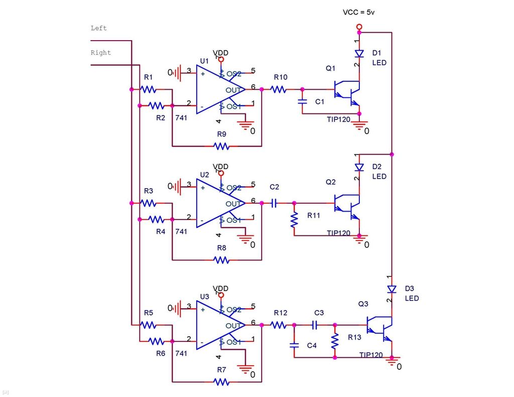
It is possible to synchronize the LEDs so that the speakers continue to play loudly while the LEDs are not always illuminated during music playback. The individual has a solid understanding of electrical concepts and is seeking a method...
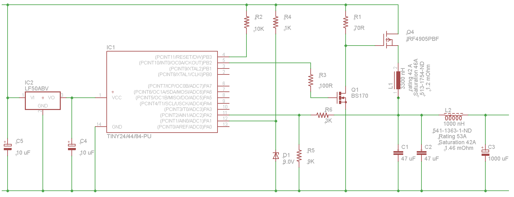
The microcontroller will not be able to drive the gate of Q1 effectively, as GPIO pins typically can only source a few milliamps, resulting in slow turn-on and turn-off times. This limitation will affect the performance of the high-side...
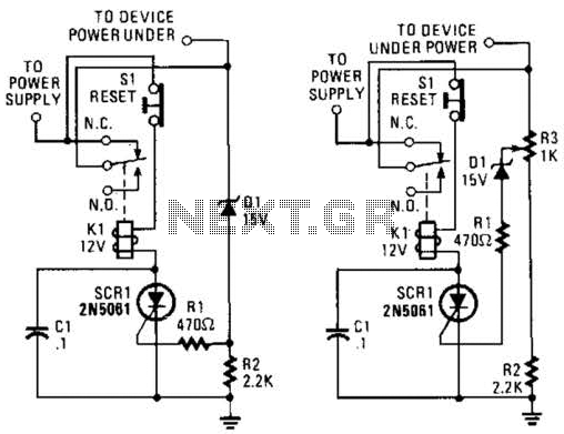
If circuits experience frequency overvoltage conditions, continually replacing blown fuses can become quite costly. This shutdown circuit addresses that issue by substituting the fuse with a relay and a low-current SCR. When the input voltage exceeds the threshold established...

This is a circuit using the LM3914 LED VU meter. It utilizes the LM3914 integrated circuit (IC1) along with a BC109C transistor. The circuit displays the level of audio signals (power music) in decibels (dB) across six levels using...
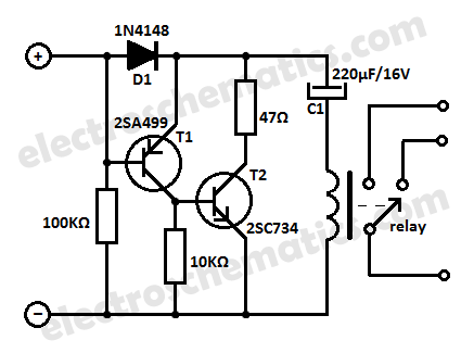
This low current relay circuit is designed for use in battery-operated electronic devices. Its operating current is in microamperes (µA). This is achieved by using a bistable relay and incorporating additional components to enable the relay to function like...
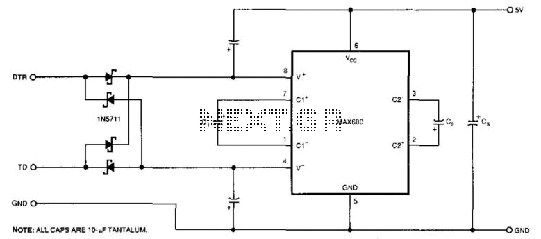
The circuit demonstrates a method for powering CMOS integrated circuits (ICs) using RS-232C lines. The MAX680 is typically employed to generate a voltage equal to ±2 Vcc. This circuit operates in the opposite manner, accepting ±10.5 to ±12V from...