power failure alarm circuit
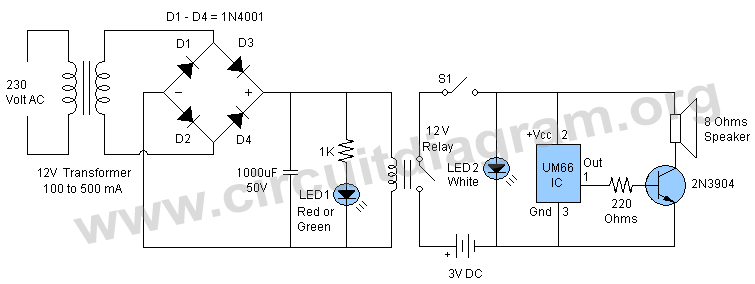
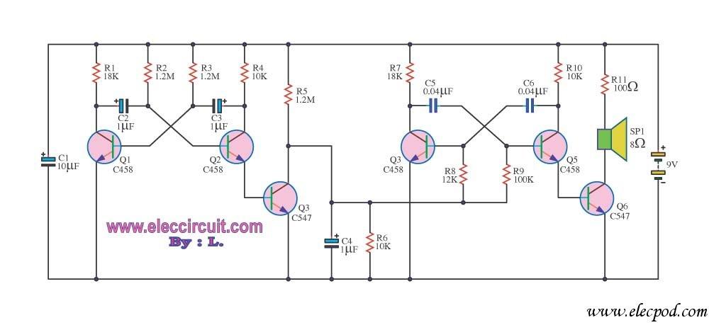
A 12-volt relay is connected between two stages such that when it receives 12 volts from the supply, it activates and disconnects the 3-volt DC supply from the melody circuit. Conversely, when mains power is absent, the relay switches off and connects the battery from the alarm circuit, activating LED2. The circuit utilizes two LEDs; a red or green LED can replace LED1, while LED2 is a white LED. The red LED indicates the presence of mains power, and the white LED automatically activates in the absence of mains power, illuminating a small area for visibility in the dark. For instance, if there is an issue with the mains supply at night, and all lights go out, the white LED will turn on, providing light to assess the situation. A separate 3-volt power source or battery is used for the alarm circuit, which can consist of two AAA or AA cells of 1.5 volts or a small 3-volt lithium button or coin cell. These batteries have a long lifespan since they are completely disconnected from the circuit when mains power is present.
The described circuit employs a 12-volt relay as a key component that facilitates the switching between two power sources based on the availability of mains electricity. When the mains power is operational, the relay is energized, allowing the 12 volts to flow through, which in turn disconnects the 3-volt supply from the melody circuit. This design ensures that the melody circuit does not interfere with the alarm function when the mains power is available.
In the absence of mains power, the relay deactivates, reconnecting the 3-volt battery to the alarm circuit. This transition is crucial for maintaining functionality during power outages. The alarm circuit is equipped with two LEDs for visual indication. The red or green LED (LED1) serves as a power indicator, illuminating when mains power is present, thus providing a clear visual cue of the system's operational status.
The white LED (LED2) plays a significant role in emergency situations, automatically activating when the mains supply fails. Its purpose is to provide illumination, enabling users to navigate or troubleshoot issues in low-light conditions, such as during nighttime outages. This feature is particularly valuable for enhancing safety and visibility in the event of a power failure.
For the alarm circuit, a dedicated 3-volt battery source is employed, which can be configured using various battery types, including two standard AAA or AA cells or a compact lithium button cell. The choice of battery type allows for flexibility in design and implementation, accommodating different user preferences and availability. The circuit's design ensures that the battery remains disconnected during normal operation, thus extending its lifespan and minimizing unnecessary power drain.
Overall, this circuit design effectively combines power management and emergency signaling, ensuring reliable operation and user awareness in both normal and power outage conditions.A 12 volt relay is connected between the two stages in a way as when it will get 12 volts from the supply it will get activated and disconnect the 3 volt DC supply from the melody circuit and in the opposite condition when mains power is absent it will become in the off condition and connect the battery from the alarm circuit and activate the LED2 and alarm circuit. The circuit is using two LEDs, you can use red or green LED in the place of LED1 and white LED in the place of LED2. The red one will indicate the presence of mains power and the white one will automatically activate in the absence of mains power and also light up a small area so you can see in the dark.
For example at night times when any problem happens in the mains supply then suddenly all lights goes off and the house become completely dark, in that case the white LED will activate and provide light from which you can watch any problem in the mains supply. A separate power source / battery of 3 volt is used for the alarm circuit, you can use any type of battery for example two AAA or AA cells of 1.
5 volts or you can also use small lithium button cell or coin cell of 3 volt. These batteries will last very long because in the presence of mains the batteries will totally disconnect from the circuit. 🔗 External reference
