
Voltage Monitor Circuit

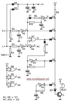
The adjustable voltage monitor circuit functions as a reliable tool for monitoring voltage levels within a specified range. It primarily utilizes an operational amplifier (U1-B) configured as a comparator. The circuit is designed to illuminate LED1 when the monitored DC voltage falls below a predetermined threshold set by the reference voltage at pin 5 of the operational amplifier. This feature serves as a visual indicator of under-voltage conditions that may affect circuit performance.
Conversely, when the monitored voltage exceeds 5V, LED2 activates, providing a clear indication of over-voltage conditions. The thresholds for these indicators are determined by the resistor values of R4 and R5, which create a voltage divider that establishes the reference voltage levels for the operational amplifier. In scenarios where the monitored voltage resides within the safe operating range defined by these resistors, neither LED will illuminate, indicating that the voltage levels are stable and within acceptable limits.
The circuit's utility extends to various applications where voltage monitoring is critical, such as power supply regulation, battery management systems, and protection circuits for sensitive electronic components. By providing immediate visual feedback through the LEDs, the adjustable voltage monitor enhances the reliability of electronic systems by allowing for prompt corrective actions in the event of voltage irregularities. The adjustable voltage monitor can be used to check whether the voltage in a circuit remains within a given range. If the dc voltage is less than the voltage at pin 5 of-Ul-B, then LED 1 will light. If the voltage is over 5V, LED2 will light. If the voltage is within the window set by R4 and R5, neither LED will light. This circuit is useful as an under-or-over voltage monitor.
Related Circuits
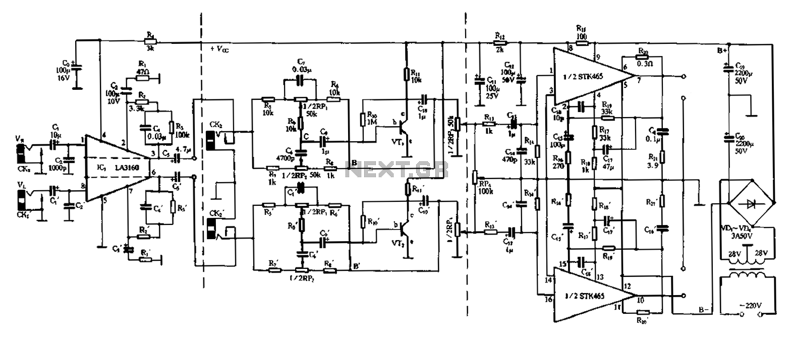
The 50W is a two-channel amplifier featuring a preamplifier and tone control based on the LA3160 integrated circuit. Its external components include the input preamplifier, with C1 serving as the input coupling capacitor. The circuit incorporates a high-frequency bypass...
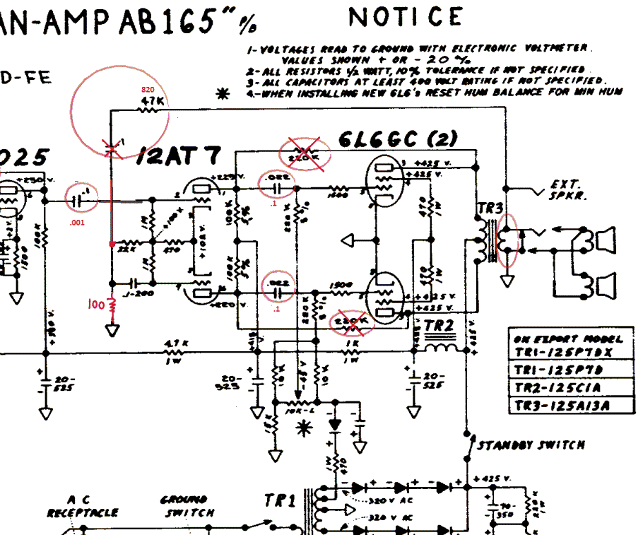
The Fender Bassman is a legendary guitar amplifier recognized by both guitar and bass players. Introduced in 1951, it was primarily aimed at bass guitar players and marketed as a bass amplifier for the Fender Precision Bass guitar, the...
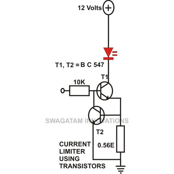
This article compiles small transistor circuits and configurations suitable for beginners, including current amplifiers, limiters, oscillators, and latches. A simple current amplifier circuit can be constructed using just a couple of NPN transistors. Additionally, two transistors and resistors can...
The circuit is designed to ensure that the headlights or side lights are automatically switched off after the ignition contact is turned off. This prevents the occurrence of a dead battery due to headlights being inadvertently left on. The circuit...
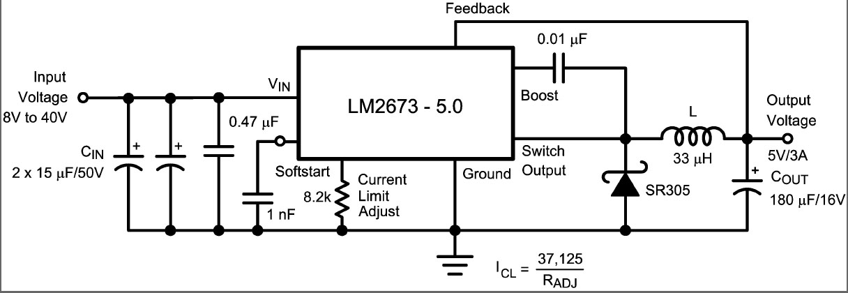
This is a DC switching regulator with an output voltage of 5V and a maximum current of 3A. It is designed for use in digital circuits. The key component of the circuit is the LM2673, which is a 3A...
A common issue with small flashlights is the limited lifespan of both the batteries and the bulb. For example, a typical incandescent flashlight consumes approximately 2 Watts, while the LED flashlight shown in Fig. 1 consumes only 24 mW....