
Ambulance sirens circuit

The circuit functions as a siren simulator by utilizing a combination of transistors to generate varying frequencies that mimic the sound of an ambulance siren. The low-frequency production stage employs transistors Q1 and Q2, which work in conjunction with resistors R2, R3, and capacitors C2 and C3 to create a modulating waveform. The output of this section is then fed into transistor Q3, which acts as a buffer to prepare the signal for the high-frequency section.
In the high-frequency production stage, transistors Q4 and Q5 operate alongside resistors R8 and R9 and capacitors C5 and C6 to generate a higher frequency signal. This high-frequency output is critical in achieving the characteristic sound of an ambulance siren. The signal from Q5 is then passed to Q6, which amplifies the combined low and high-frequency signals to a level suitable for driving a speaker.
Capacitors C1 and C4 are strategically placed to filter the output, ensuring that the sound produced is clear and free of unwanted noise. Resistor R11 is included to safeguard the speaker from excessive current, thus preventing potential damage during operation. Overall, this circuit design provides an effective and customizable solution for generating ambulance siren sounds using discrete components rather than integrated circuits.This circuit is a circuit that sounds a siren-like sound of ambulance sirens. This circuit is different to an ambulance siren circuit generally, is to use transistors instead of IC 555. Which allows economical and easy to tailor a network. Operation of the circuit. This cycle can be divided into three main parts is the low frequency production. Pr oduction of high frequency. The amplifier. The manufacture low-frequency includes Q1, Q2, R2, R3, C2, C3. Which will produce low-frequency out and to extend the Q3. Before you sent with high frequency of origin from Q4, Q5, R8, R9. , C5, C6 signal is included, then the output will come out to the leg E of the Q5. and then be expanded with Q6 to drive the speakers. The C1, C4 is intended to stir filter collects them. The R11 will help prevent speaker damage. 🔗 External reference
Related Circuits
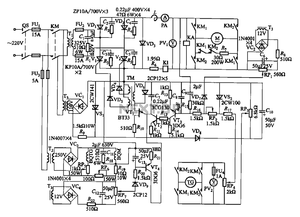
The circuit encompasses a main circuit, a trigger circuit, speed negative feedback, negative feedback differential voltage, a current cut-off circuit, loss of field protection, and other components. Given that the motor power is small (1.1 kW), a single-phase circuit...
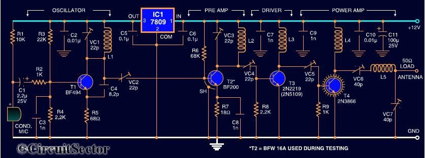
Here is the circuit diagram of a four RF stage FM transmitter. The stages include a very high frequency (VHF) oscillator built around the HF transistor BF494, a pre-amplifier using the BF200 transistor, a driver transistor 2N2219, and a...
The RF power amplifier circuit described here utilizes the transistors 2SC1970 and 2N4427. This FM RF amplifier operates within the frequency range of 88-108 MHz, delivering an output power of approximately 1.3W from an input driver of 30-50mW. The...
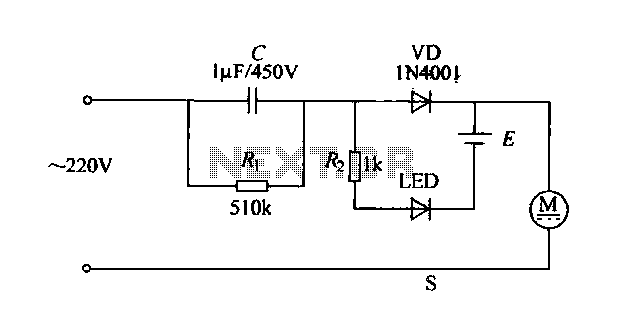
The electric shaver circuit is illustrated in Figure 1-17. It features a buck capacitor (C) rated at 1 µF and 450V, which connects through diode VD to charge 1.2V nickel-cadmium batteries. Additionally, after the buck converter, there is a...

This is a circuit design for a doorbell that produces a sound resembling that of a bird. The circuit is controlled by an NPN transistor. The operation begins when P1 is set to an experimental value, starting with approximately...
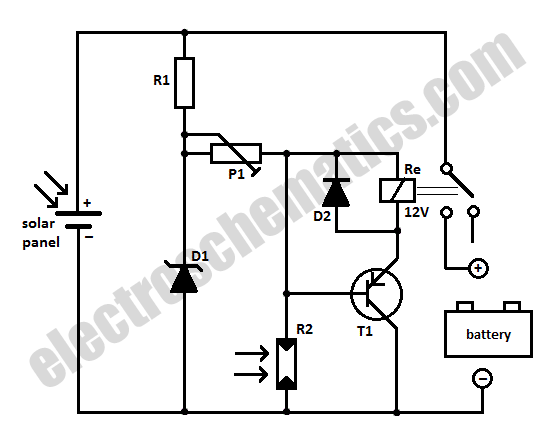
When charging a battery during the day using a solar panel, there is a risk of the battery partially discharging through the panel after sunset. This solar panel power switch circuit eliminates the need for a diode by utilizing...