
power mosfet circuit
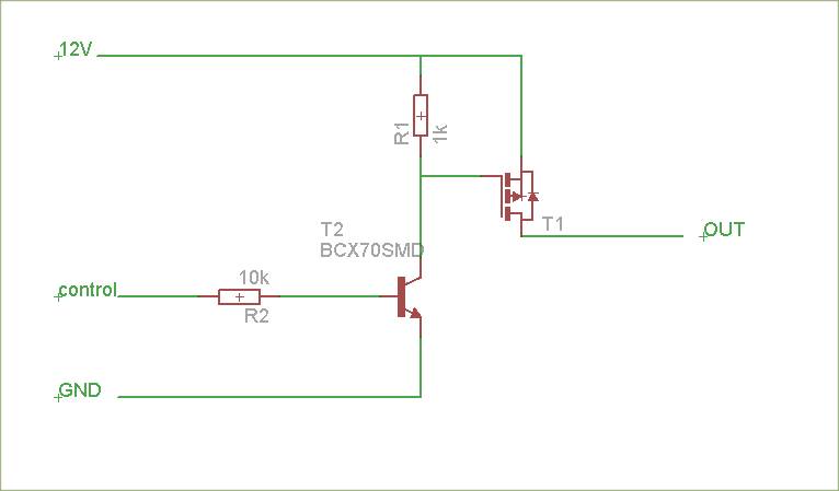
In the proposed circuit, the P-channel MOSFETs serve as the primary switching elements for controlling the output voltages. It is crucial to ensure that the gate-source voltage (Vgs) is correctly managed to achieve the desired ON and OFF states of the MOSFETs. When the gate voltage is lower than the source voltage by the threshold voltage of the MOSFET, the device will turn ON, allowing current to flow from the source to the drain. Conversely, when the gate voltage is equal to or higher than the source voltage, the MOSFET turns OFF, interrupting the current flow.
To implement reverse polarity protection, a common solution is to introduce a diode in series with the power supply. This diode will block any reverse current that could damage the MOSFETs or other components in the circuit. An alternative method is to use a P-channel MOSFET in a high-side configuration, which can also provide reverse polarity protection when correctly biased.
Given that the switching frequency is low (less than 1 kHz), the design can be simplified by removing components that are necessary for high-frequency operation. This includes reconsidering the need for a fast MOSFET driver, which may not be required for applications that do not demand rapid switching. Instead, a simpler approach could involve directly driving the gate of the P-channel MOSFET using a resistor and a pull-down configuration to ensure that the gate is pulled to ground when the control signal is low.
In summary, the circuit can be optimized by ensuring proper gate voltage management, integrating reverse polarity protection, and simplifying the driver circuitry for low-frequency applications. This approach will enhance reliability while reducing component count and complexity.The schematic is attached, I`d like to have a suggestion if any improvement could be made, in particular I`d need to add a reverse polarity connection protection. I`m not a MOSFET expert, but: from the schematic I take it that the logic level inputs (5 V) are meant to control two output voltages (12V) via P-channel MOSFETs.
1) The P-channel MOSFET s are ON (conducting) when the gate-source voltage is negative. This means that the MOSFET will be OFF when the output of the MOSFET driver is high (12 V). See datahseet of the MCP14E3, table 4-1. I don`t know whether you are aware of this and whether this is the intended behaviour. 2) The MOSFET driver circuit is meant for fast switching operation. Do you really need to switch power very fast If you are only going to switch power on and off now and then (meaning at less than e. g. 1 kHz), you can simplify the circuit tremendously: 🔗 External reference
Related Circuits
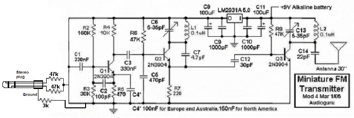
This small FM transmitter can be modified to replace the microphone with an audio jack, allowing it to connect to an MP3 player for audio playback through car audio systems. The design is straightforward and intended for a short...
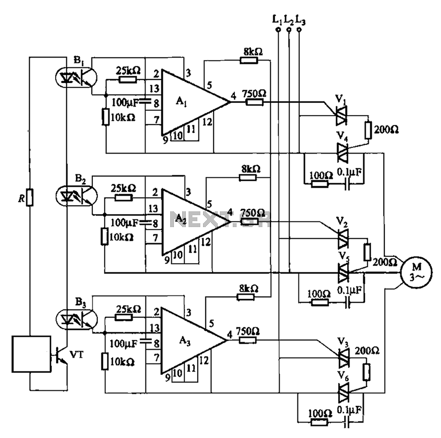
The 331 circuit depicted in the figure utilizes a two-way thyristor for controlling the start and stop functions of a motor. It operates without mechanical contacts, generating no noise or sparks, making it suitable for applications that require frequent...
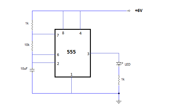
The NE555 is one of the most commonly used timer integrated circuits (ICs). It is a monolithic timing circuit capable of producing accurate and highly stable time delays or oscillations. Similar to general-purpose operational amplifiers, it is reliable, easy...
The circuit-delay relay for speakers serves as a delay mechanism that prevents the immediate activation of speakers when the amplifier is powered on. This feature is designed to protect the speakers from potential damage caused by sudden power surges....
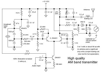
In many discussions of LPAM transmitter design, references to "the Wenzel circuit" or "the Wenzel transmitter" are common. These terms refer to a clever transmitter design that became popular in the mid-1990s and early 2000s for those interested in...
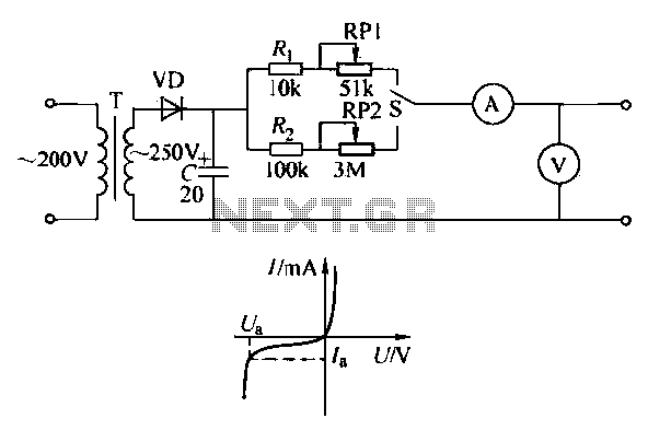
To ensure proper operation of the transistor in a circuit, it is essential to measure the reverse breakdown voltage of the transistor. This is particularly important for tubes with high reverse breakdown voltage requirements, such as those used in...