
Circuit Delay and Speakers Protektor Using TL071

The circuit-delay relay for speakers is an essential component in audio systems, particularly to enhance the longevity of speaker systems by preventing damage due to immediate power application. When the amplifier is turned on, the relay remains open for a predetermined delay period, allowing the amplifier to stabilize before connecting the speakers. This is crucial in avoiding the 'thump' sound that can occur when speakers are powered on too quickly, which can lead to physical damage over time.
The schematic typically includes a relay, a resistor, and capacitors, with C2 being the primary component for time adjustment. The relay is selected based on the current and voltage ratings suitable for the specific speaker and amplifier configuration. The resistor limits the current flowing through the relay coil, ensuring that it operates within safe parameters.
In the event of a short circuit between the amplifier and the speakers, the relay is designed to disconnect the speakers almost instantaneously, providing a layer of protection against potential hazards such as overheating or fire. The circuit's delay mechanism can be tailored to specific requirements by adjusting the capacitance of C2, allowing for flexibility in different audio setups.
Overall, the circuit-delay relay circuit is a practical solution for enhancing the reliability and safety of audio systems, making it a valuable addition for both amateur and professional audio engineers.Circuit-delay relay circuit speakers is useful as a delaying / delay on the speaker that functions as a deterrent to prevent pounding of the very first amplifier is turned on. This aims to avoid memperawet speakers easily damaged. The following is a schematic drawing : This series also has advantages, namely: the case of speakers konsleting relat
ionship with amplifier circuit will be disconnected immediately, so that the speaker is safe from kebakaran. waktu waiting or delay time is approximately 5 seconds, and can be altered by changing the condenser C2 with elco smaller value.
The time needed to re-open relay if the current cut off about 0. 5 seconds. Or you can try to use the circuit scheme below: 🔗 External reference
Related Circuits
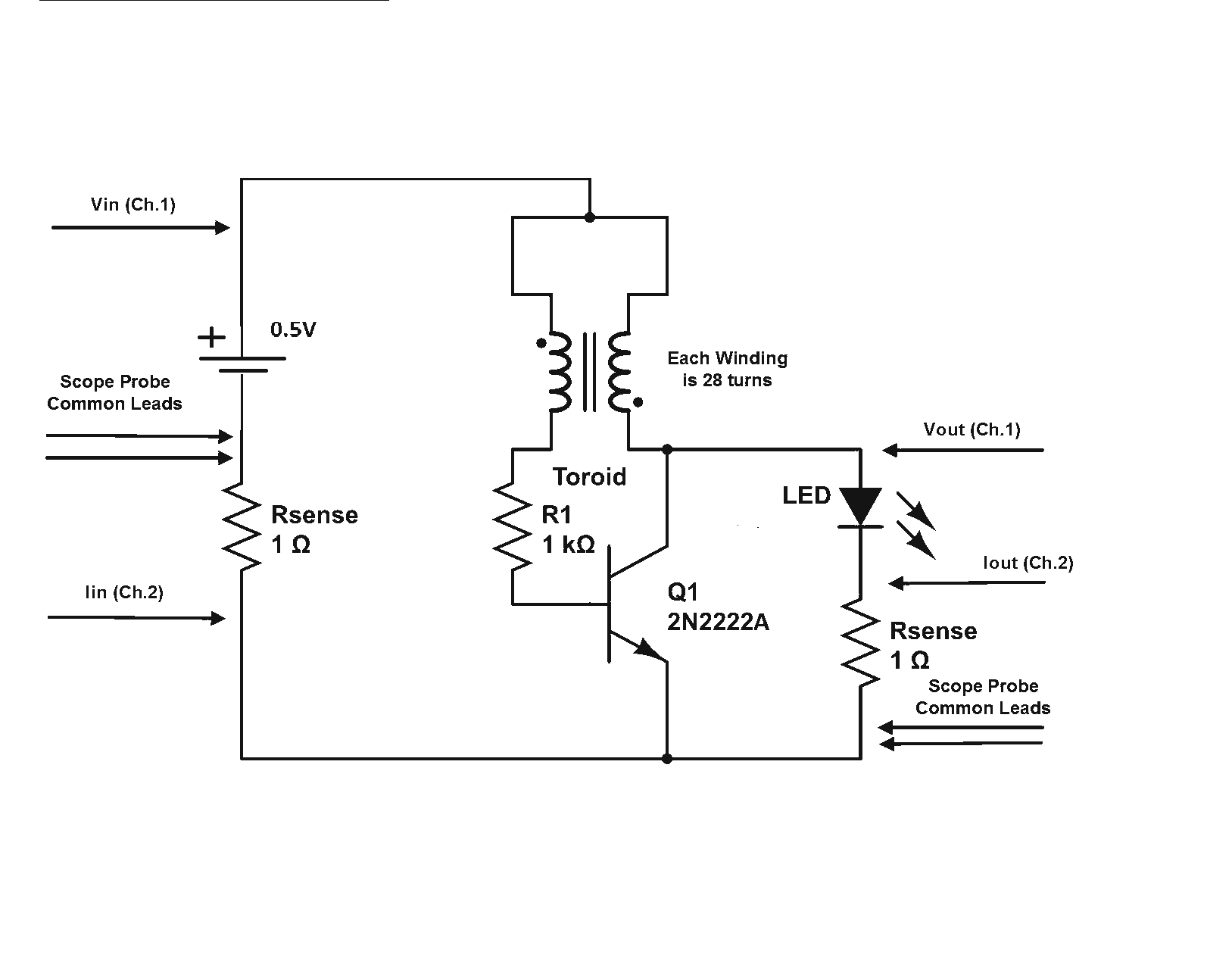
Is a Joule Thief circuit capable of achieving overunity? Joule Thief schematic including scope measurement points. The Joule Thief is a minimalist circuit designed to extract energy from low-voltage sources, such as depleted batteries, and convert it into a usable...
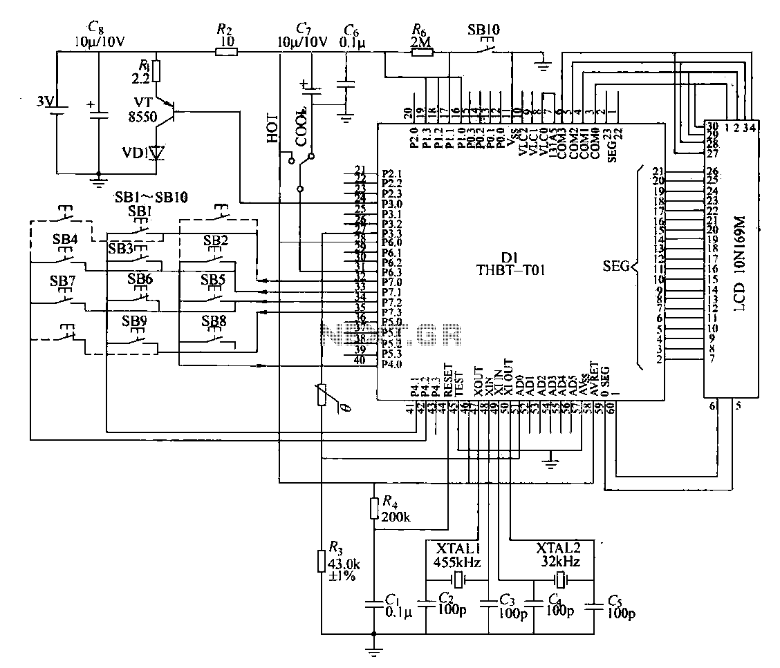
The circuit composition of a specific remote control transmitter is illustrated in a diagram. The transmitter primarily consists of a large-scale integrated circuit chip (D1, THBT-T01), a 4.5 kHz crystal oscillator, a 32 kHz crystal oscillator, a liquid crystal...
The Electronic Dazer is a modern, portable, personal-protection appliance. It generates high potential energy to ward off vicious animals or other attackers. It is an aid to help escape from a potentially dangerous situation. The device develops about 2,000...
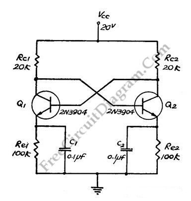
This flip-flop circuit functions as a free-running astable multivibrator, where the bases and collectors of both emitter-biased transistors are directly coupled. The switching action is facilitated by a capacitor in each emitter circuit, resulting in the generation of triangle...
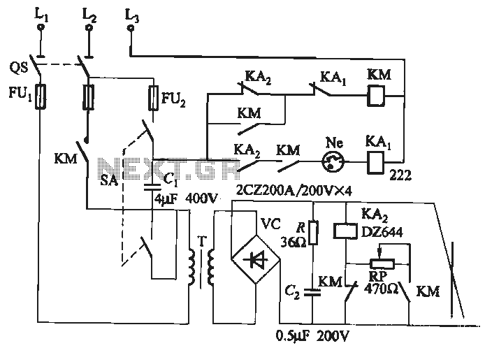
A single-phase rectifier DC welding power load from the road circuit is presented. The contactor KM utilizes a CJ20-40A model rated for 220V. An adjustment potentiometer RP is employed to ensure proper arcing, while the relay KA2 is designed...
This is a remote tester circuit designed to test TV and other remote controls. The circuit is simple and utilizes only a few components. The infrared sensor used in the circuit is the TSOP1738. When the infrared waves are...