
modifying fm transmitter circuit 3
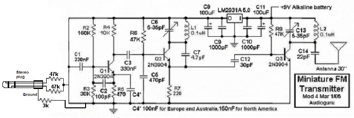
For the construction of this FM transmitter, careful attention should be paid to the choice of components and their arrangement. The circuit requires an RF buffer amplifier transistor to ensure that the RF oscillator operates independently from the antenna, preventing signal degradation. A low-dropout voltage regulator, such as the LM2931A5.0, is recommended to maintain a stable voltage supply, ensuring the circuit functions correctly even when the battery voltage decreases to around 5.6V.
When designing the circuit layout, it is crucial to use a printed circuit board (PCB) or a tightly arranged Veroboard to minimize interference and ensure reliable operation at high frequencies. The use of ceramic capacitors is advisable due to their low equivalent series resistance (ESR) and stability across varying temperatures and voltages, which is vital for maintaining consistent performance in an FM transmitter.
The overall cost of components for this project is relatively low, making it an attractive option for hobbyists and those looking to gain practical experience in electronics. The basic circuit diagram should include clear labels for input and output connections, which are typically denoted as I and O, respectively. As this is an introductory project, it is recommended to start with a kit that includes all necessary components and instructions for assembly, allowing for a smoother learning experience.To this small FM transmitter to change the mic for an audio jack so I can plug it into my mp3 player to listen to songs on my car audio. I looked at some of the transmitters on this site, but I think I`m going to go with this one, as I find it simple, and only need like 10 feet range (not even probly.
) rip out the mic, connect the base of the transistor to a capacitor. Now connect the other end of the capacitor and the -ve to your MP3 player speaker output. A 0. 22uF coupling capacitor from the MP3 player is fine. You should connect both stereo outputs from the MP3 player each to a 47k series resistor. Connect both 47k resistors to the coupling capacitor and a 0. 1uF capacitor can be used. Connect the grounds of the MP3 player and transmitter together with the shield of audio cable and the audio signal inside it. It is not necessary to connect the MP3 player`s output "backwards". Just connect its output to the coupling capacitor added to the transmitter and connect the grounds together.
That FM transmitter is so simple that its radio frequency will change all over the place if you get near it, if the battery voltage changes or if the temperature changes. Since it doesn`t have pre-emphasis (treble boost) like radio stations have and radios have the opposite, reception from it will sound muffled without treble frequencies.
:lol: Also, "connect the grounds of the mp3 player and transmitter together with the shield of the audio cable and the audio signal inside it" I`m not sure what your saying there. and what ground from the mp3 player Anyway, I`m really short on cash, and I`m doing this more for the learning experience than actually using it (although I probly will use it.
). Also, I`ve read that you have to use ceramic capacitors for transmitters like this. just checking if thats true. 2) The battery voltage. The transistor`s capacitance changes with voltage so that it performs frequency modulation. When the battery`s voltage changes then so will the transistor`s voltage. My FM transmitter project works perfectly. I used an RF buffer amplifier transistor to isolate the RF oscillator from the antenna. I used a low-dropout voltage regulator so that the 9V battery`s voltage can drop to less than 6V before the RF frequency is affected. I used low distortion circuitry and pre-emphasis so that the sound is superb. It goes more than 2km though, which is too far for your application. The day after another guy built it, he saw the RF cops in their truck with the antennas on top slowly go down his street.
I told him they were looking for me! Hi again, I haven`t been able to get parts to build anything yet, cause the last place in town to sell components was Radio Shack, which became The Source, and no longer sells components. anyway, because of the delay, I was thinking I might build your transmitter instead Audioguru, but I was wondering how I`d go about making the range small enough to be legal (and how to change it to use audio input from MP3 :wink: ).
Also, just wondering if you could give me an estimate of how much it cost to get the parts needed to build it (and what is the box with I O on it. I`m really new to this, I know the basics of circuit diagrams and stuff from school, but haven`t really made any cicuits myself before) I removed the mic and R1 to test it.
I made an input attenuator with two 47k resistors from each channel of my music source to a 3k resistor to ground. Of course the grounds were also connected together. The LM2931A5. 0 is a low-dropout 5V voltage regulator IC that allows the circuit to continue working well when the battery voltage drops to about 5.
6V. I = its input and O = its output. Circuits that operate at these very high frequencies need a pcb or a very tight Veroboard layout. Perhaps it would be best for you to make a kit as your 1st project. :lol: 🔗 External reference
Related Circuits
This transmitter can be utilized for multiple applications. An INS8048L microprocessor produces various codes based on keypad inputs. These codes are modulated onto a 40-kHz carrier frequency. Additionally, Q1 drives infrared LEDs LED1 and LED2. The transmitter circuit primarily consists...
A compact power amplifier that delivers high-quality sound. It incorporates a NE5534 operational amplifier, known for its excellent performance, capable of handling low loads, providing high speed, and exhibiting low distortion. Additionally, it features two V-MOSFET transistors at the...
Constructing an FM transmitter for the first time can be challenging due to confusion regarding the necessary components, parts, design, PCB layout, and transmission aspects. An FM transmitter is an electronic device that encodes audio signals into radio frequency waves,...
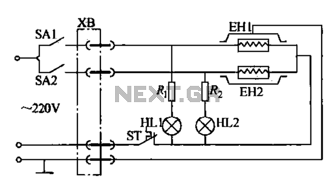
Currently, the use of cookers has become fashionable due to their speed, cleanliness, and low pollution levels, making them a favorite among consumers. Cookers circuit. The modern cooker circuit typically involves a combination of heating elements, control systems, and safety...
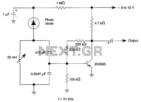
The circuit utilizes a tuned circuit for frequency selection, designed to operate at approximately 51 kHz. The 2N3565 transistor amplifies the output generated by the tuned circuit. The described circuit operates on the principle of resonance, where the tuned circuit...
An LED flasher circuit can be constructed using a 555 integrated circuit (IC). The use of the 555 IC allows for greater flexibility in adjusting the flashing rate of the LED. This LED flasher circuit is similar to other...
Warning: include(partials/cookie-banner.php): Failed to open stream: Permission denied in /var/www/html/nextgr/view-circuit.php on line 713
Warning: include(): Failed opening 'partials/cookie-banner.php' for inclusion (include_path='.:/usr/share/php') in /var/www/html/nextgr/view-circuit.php on line 713