
pwm with microcontroller 8051 for scr

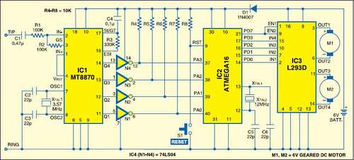
This project involves a microcontroller-based PWM signal generation system that can be adapted for various applications, including control of SCRs and TRIACs for power management. The primary function of the system is to produce two PWM signals, which can be expanded to accommodate additional outputs as required by the application. The microcontroller receives 100Hz pulses that serve as zero-crossing detection signals, which are essential for synchronizing the PWM output with the AC mains frequency.
The two-channel Digital-to-Analog Converter (DAC) configuration allows the microcontroller to convert digital signals from its ports (port 1 and port 2) into analog voltages ranging from 0 to 5V. This voltage range is suitable for interfacing with various electronic components, ensuring that the output signals are compatible with standard control devices.
In scenarios where control of an SCR is necessary, the design incorporates an optocoupler, specifically the MOC3020, to provide electrical isolation between the microcontroller and the high-voltage SCR circuit. The optocoupler allows for safe operation by preventing high voltages from affecting the microcontroller while enabling the control of the SCR or TRIAC.
The programming aspect of the project utilizes the Keil compiler for developing the C code that governs the PWM signal generation. This code is responsible for determining the duty cycle and frequency of the PWM signals, which can be adjusted based on the requirements of the load being controlled. The flexibility of the PWM configuration allows for efficient power control in various applications, ranging from motor control to lighting dimming systems.
Overall, this project exemplifies a robust approach to PWM signal generation and power control through the integration of microcontroller technology, analog interfacing, and component isolation techniques.This project is currently output two PWM signals but can be extended to many PWM signals very easy. The input to the microcontroller is 100HZ pulses as zero crossing. currently it is build for two channel DAC, the input at port1 and port2 of microcontroller is converted to 0 - 5v accordingly. But if it is desired to control the SCR, then OP-AMP ci rcuit will be removed and optocoupler moc3020 will be used for interfacing SCR or triac. The code of program for PWM with microcontroller 8051 for SCR or triac power control is written c lanuage using keil compiler. The c-code for PWM is as follows. 🔗 External reference
Related Circuits
This instructable is categorized under 13 - 18 in the National Robotics Week Robot Contest. The National Robotics Week Robot Contest encourages innovation and creativity in robotics among participants aged 13 to 18. This category represents a significant opportunity for...

This article continues from the previous one regarding the single character LCD display using an AVR microcontroller. The prior article demonstrated how to display a single letter on an LCD. This article advances the learning process by explaining how...

The Universal Timer is a highly versatile timer project that accommodates a wide range of time periods, from 1/10th of a second to 100 hours. This circuit diagram includes a comprehensive description of various timer circuits associated with the...
Schaer is a generic programmer circuit capable of uploading and downloading firmware to and from several electronic devices, such as microcontrollers. The Schaer programmer circuit is designed to facilitate the transfer of firmware between a host computer and various electronic...
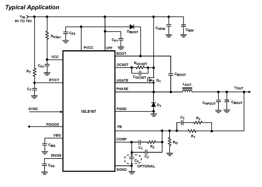
The ISL8107 is a single-phase, non-synchronous buck controller equipped with an integrated high-side MOSFET driver. It operates within an input voltage range of 9V to 75V. The internal reference voltage is 1.192V with a tolerance of ±1% across the...
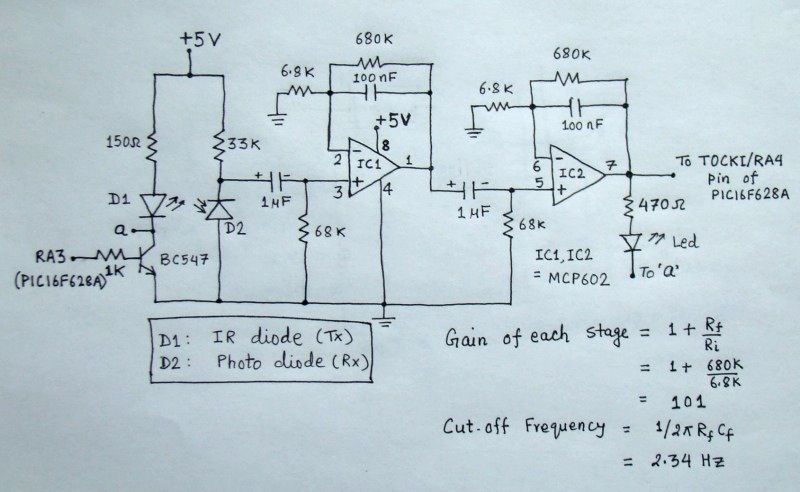
The reflected infrared (IR) signal detected by the photodiode is sent to a signal conditioning circuit, which filters out unwanted signals and amplifies the desired output. The circuit begins with a photodiode that captures the reflected IR signals. The photodiode...