
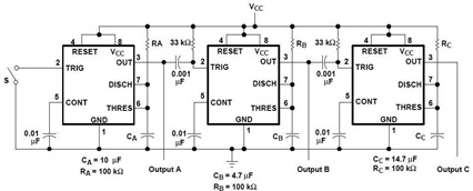
sequential timer circuit diagram using 22
The NE555 timer IC is a versatile component widely adopted in electronic circuits for timing applications. It can operate in three modes: astable, monostable, and bistable. In the astable mode, the NE555 generates a continuous square wave output, while in monostable mode, it produces a single pulse when triggered. The bistable mode allows the circuit to maintain its state until it receives a trigger signal to change states.
In a sequential timer circuit, the NE555 can be configured in monostable mode to create a series of timed outputs. Each output can be connected to a subsequent stage of the circuit, allowing for precise control over the timing of each event in the sequence. By adjusting the resistor and capacitor values in the timing circuit, the duration of each output pulse can be finely tuned to meet specific application requirements.
The flexibility of this circuit allows it to be employed in a range of systems, from simple test equipment to more complex automation processes. The ability to use modulation techniques enables designers to create varying waveform outputs, further enhancing the circuit's functionality. The NE555 datasheet provides comprehensive specifications and application notes, which are essential for understanding the full capabilities of this IC in sequential timer applications.
In summary, the sequential timer circuit utilizing the NE555 timer IC is an invaluable tool in electronic design, providing reliable timing control for a multitude of applications. Its adaptability and precision make it a preferred choice for engineers and designers seeking to implement sequential control in their projects.A sequential timer circuit device are used in many applications for initializing conditions during start-up or for activation of test signals in sequences such in test equipment device. The circuit diagram below shows a sequencer circuit with possible applications in many sistems. As you can see, it uses the NE555 precision timer IC which capable of producing accurate time delays or oscillation. These timing circuits can be connected to provide such sequential control with various combinations of astable or monostable circuit connections. You can used it with or without modulation for extremely flexible waveform control. You may see the NE555 Datasheet here (source: ) 🔗 External reference
Related Circuits
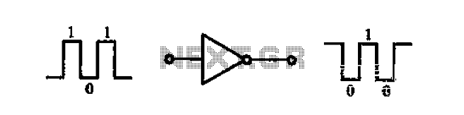
A common-emitter transistor amplifier produces an output signal that is 180 degrees out of phase with the input signal, commonly referred to as an inverting amplifier. When the electrical path for amplifying the pulse signal is activated, this circuit...
This simple and inexpensive circuit built around a popular CMOS hex inverter IC CD4069UB offers four sequential switching outputs that may be used to control 200 LEDs (50 LEDs per channel), driven directly from mains supply. Input supply of...
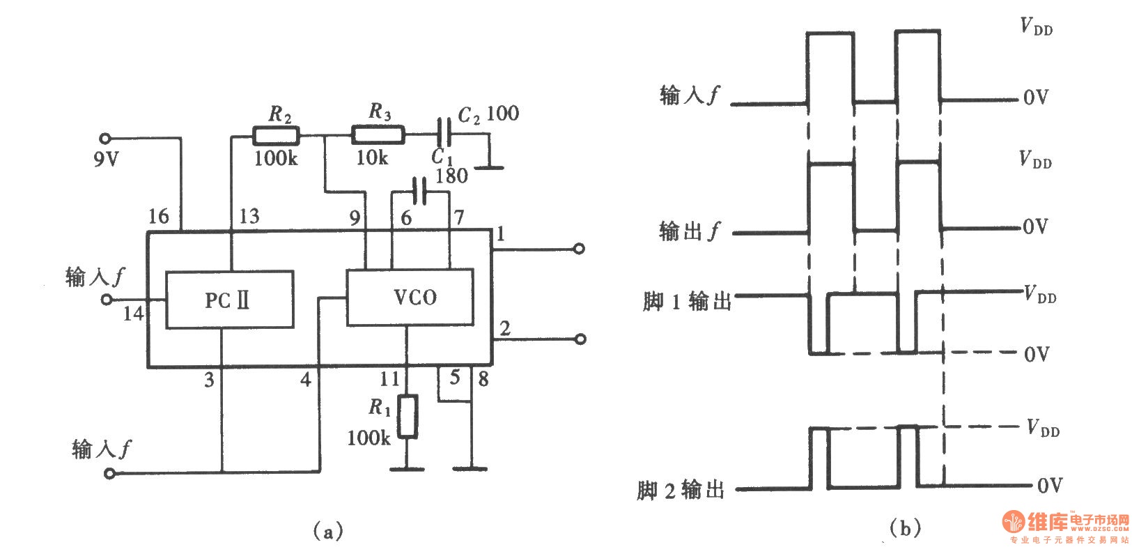
A frequency signal tracking circuit is implemented using a phase-locked loop (PLL) configuration, which is a fundamental application of the CD4046 integrated circuit. The circuit, illustrated in the accompanying chart, utilizes the CD4046 to form a PLL that effectively...
I designed up this circuit board because of a request from a visitor to my website. I also assemble the circuit board to verify the board was correct. It does work, very nicely, but I have no way to...
Implementing tactile (haptic) feedback in consumer electronic devices enhances the user experience by providing a sense of touch in user interface design. It represents the latest major interface innovation in smartphones and other portable consumer electronic devices. Various haptic...
This is an LM338-based power supply that is uncomplicated and easy to construct. It has been in use for an extended period without any issues. The circuit lacks a current adjustment feature, which has been addressed by incorporating an...