
temperature sensor circuit

The temperature sensor circuit utilizes a thermistor, which is a critical component that responds to temperature changes by altering its resistance. This property allows it to function effectively in detecting thermal variations. The BC547B transistors, arranged in a Darlington configuration, provide a significant amplification of the current, thereby increasing the circuit's sensitivity to small changes in temperature. The Darlington pair is particularly advantageous in applications where a higher gain is required, enabling the circuit to respond to subtle temperature shifts.
The LED serves as a visual indicator, illuminating when the circuit detects a sufficient increase in temperature. The current-limiting resistor is essential to prevent excess current from damaging the LED, ensuring longevity and reliable operation. The inclusion of a 20K variable resistor allows for fine-tuning of the circuit's response, enabling the user to set the desired activation temperature for the LED.
In summary, this simple temperature sensor circuit is an effective solution for heat detection, leveraging the properties of a thermistor and the amplification capabilities of a Darlington pair to provide a reliable output in the form of an illuminated LED. The design is user-friendly and can be easily assembled with minimal components, making it suitable for various applications in temperature monitoring and alarm systems.The schematic shown here is a project of a simple temperature sensor circuit or we can also say it a heat sensor circuit, which will activate an LED when receive heat. The circuit is easy to make and using only few components. The two BC547B transistors are connected as a darlington pair to increase the sensitivity of the circuit.
Other components of the circuit are an LED, a current limiting resistor for LED, a 20K variable resistor and a thermistor. A thermistor is a device that limits the passing of current through it according to the temperature. In the condition of low temperature they have higher resistance and in the opposite condition when they receive heat their resistance starts decreasing rapidly and current starts to flow.
Working of the circuit is simple when the thermistor will receive heat its resistance will decrease due to which the transistors will become switched on and the voltage will starts passing through the transistors which will activate the LED. The 20K resistor is used to adjust the circuit to activate the LED on the required heat or temperature.
🔗 External reference
Related Circuits

The operation control circuit is primarily managed by the button switch SB21. The contactor KM1, composed of the main contactor KM1, directly controls the operation of the main motor M1. The main motor M1 serves as the prime mover,...

This circuit is designed to display the speed of a vehicle in kilometers per hour (km/h). An opaque disc is mounted on the spindle connected to the front wheel of the vehicle. The disc features evenly spaced holes along...
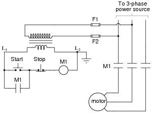
The most challenging aspect of interpreting ladder diagrams, particularly for individuals familiar with electronic schematic diagrams, is the representation of electromechanical relays. The operation of a motor control circuit should be explained, detailing what occurs when the "Run" switch...
The USB charger power supply is designed for use in MP3 and MP4 chargers. It accepts an input of AC 160-240V at 50/60Hz and has a rated output of DC 5V at 250mA. For applications requiring a long-term higher...

The loop gain of the operational amplifier (OP) is primarily influenced by the ratio of the input resistor to the feedback resistor. Consequently, any resistance error can lead to a corresponding gain error, which necessitates the use of high-precision...

This AM radio receiver circuit utilizes the TDA1083 radio IC, which is suitable for constructing a simple medium frequency (MF) band radio. The schematic operates within a frequency range of 300 kHz to 3 MHz. The circuit is straightforward...