
Precision polarity switching circuit by conventional elements

The operational amplifier circuit described focuses on maintaining accurate gain through careful selection of resistors. The loop gain is a critical parameter in determining the overall performance of the amplifier, which is affected by the ratio of the input resistor (R1) and the feedback resistor (R2). Any variation in these resistances can introduce errors in the gain, which can be detrimental to the circuit's performance.
To mitigate these errors, high-precision resistors are recommended, especially for the variable resistor (VRi), which is essential for fine-tuning the circuit's response. The design should ensure that the resistors used have a tolerance of 1% or better to maintain accuracy. In this case, R1 is specified as 9 kΩ, while R2 is set at 10.1 kΩ. The choice of these values is deliberate, as they are close to a standard value and provide a manageable range for adjustments.
The variable resistor (VRi) allows for the adjustment of the gain, and its design must accommodate the necessary precision. The gain adjustment can be fine-tuned within a narrow range, which is crucial for applications requiring high fidelity. The circuit should be laid out to minimize parasitic capacitance and inductance, which could further affect the gain stability.
In summary, the operational amplifier circuit relies on the precise ratio of resistances to ensure accurate gain. The use of high-precision resistors and careful design considerations will lead to improved performance, enabling the circuit to meet the stringent requirements of various applications. Because the loop gain of the amplifier OP depends mainly on the dry input resistor and feedback resistor ratio, so the resistance error, an error occurs opening will be a corre sponding gain in order to get more accuracy caused by four, you need high-precision resistors for o narrow range of VRI variable resistor Rs, ugly whose resistance Rl, R2 1/100, this kind of deviation can be compensated resistance, RL is actually g. 9kQ, Rz is 10.1 kQ, this worst-case scenario is very small, so VRi adjustable range of disabilities 1% is enough.
Related Circuits

This circuit exhibits an exceptionally fast high-frequency response, as demonstrated by applying a 100 kHz square wave to the input. All graphs were produced using Tina Pro. The circuit's design is optimized for high-frequency applications, showcasing rapid response times that...
An RF probe is a circuit designed for testing equipment that converts high-frequency signals into DC voltage. This conversion facilitates the measurement of RF voltages for testing or adjusting transmitters, receivers, and modulators. The RF probe circuit outlined here...
This is a simple and cost-effective inverter designed to power a small soldering iron (25W, 35W, etc.) when a mains supply is not available. The circuit utilizes eight transistors along with several resistors and capacitors. Transistors Q1 and Q2,...
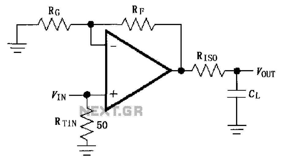
The circuit depicted in FIG demonstrates the MAX4450/4451 utilizing a capacitive load drive circuit with an isolation resistor (RISO). This configuration is situated between the output terminals and the load, along with an additional resistor, to mitigate overshoot and...
This circuit is a conventional Pierce type oscillator that utilizes a JFET. It employs fundamental mode crystals and demonstrates good performance and reliability when a low noise JFET is used. The feedback is regulated by the capacitance C1, which...
This circuit utilizes a sawtooth oscillator along with an output amplifier that drives a transistor. The components C1, C2, and L1 are essential for the oscillator's operation, forming a tank circuit that must be tuned to the resonant frequency....