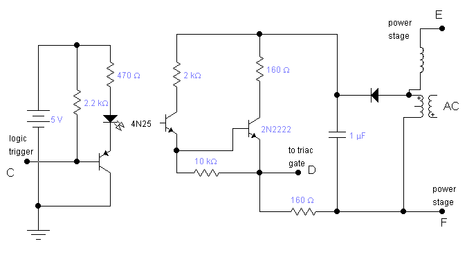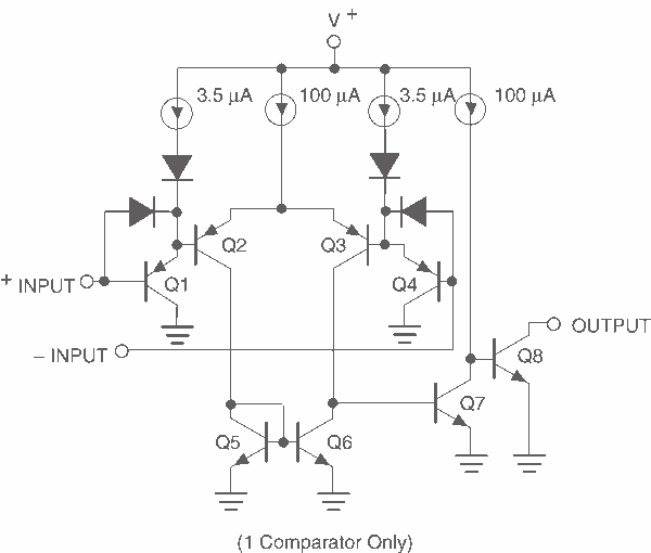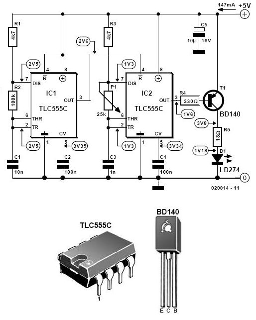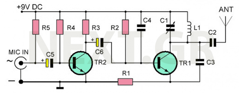
thyristor trigger circuit schematic diagram

The circuit receives its input from the zero-crossing detector, which generates a 0-to-1-to-0 pulse to set the R-S flip-flop and activate the ramp circuit (A to Ramp) to initiate the timing ramp ascent.
The described circuit operates by utilizing a zero-crossing detector, which is designed to identify the point at which an alternating current (AC) signal crosses zero volts. This detection results in a pulse that transitions from low (0) to high (1) and back to low (0). This pulse serves as a trigger for the R-S flip-flop, a fundamental digital memory element that can store a single bit of information.
Upon receiving the pulse from the zero-crossing detector, the R-S flip-flop is set, which enables it to enter a state where it can control subsequent components in the circuit. The output of the flip-flop is connected to the ramp circuit, denoted as "A to Ramp." This connection activates the ramp circuit, allowing it to begin generating a linear voltage ramp over time.
The ramp circuit typically comprises a resistor-capacitor (RC) network, which determines the rate of ascent of the voltage ramp. The values of the resistor and capacitor are selected based on the desired timing characteristics of the circuit. As the ramp circuit operates, it produces a gradually increasing voltage that can be used for various applications, such as timing, waveform generation, or triggering other circuits.
In summary, this circuit effectively utilizes a zero-crossing detector to provide a precise timing signal that controls the operation of an R-S flip-flop, which in turn initiates a ramp circuit. The design ensures reliable timing and voltage control for various electronic applications.The circuit takes its input from the "zero-crossing detector", which provides it with a 0-to-1-to-0 pulse to "set" the R-S flip-flop and release the ramp circuit (A to Ramp) for it to start the ascent of the timing ramp. 🔗 External reference

%2Band%2B(US)%2BCX500%2BC%2B1979-81%2Band%2B1979%2BCX500%2BD%2BElectrical%2BWiring%2BDiagram.jpg)


