
LAMP ELECTRICAL CIRCUIT DIAGRAM
%2Band%2B(US)%2BCX500%2BC%2B1979-81%2Band%2B1979%2BCX500%2BD%2BElectrical%2BWiring%2BDiagram.jpg "LAMP ELECTRICAL")
No description available.
Related Circuits
Figure 1 consists of a Programmable Unijunction Transistor (PUT) and an automatic interval timer circuit. In this circuit, the PUT serves as the oscillator. The switch S1 is used to toggle between interval timing and automatic timing modes. When...
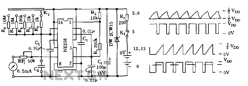
The tester comprises a dual time base circuit using a 556 timer and various RC components. The right side of the circuit features the 556 timer (556 1/2) along with resistors R2, R3, capacitors C2, C3, and additional components...

Another application of the frequency-to-voltage converter (FVC) is the tone/frequency decoder. This circuit is designed to identify the frequency band of an oscillating signal. It is utilized in various applications, such as determining the frequency band in signals and...
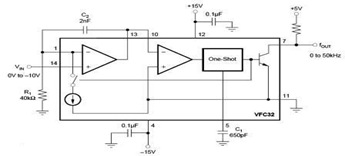
The circuit diagram of a voltage-to-frequency (V/F) converter is presented, designed to handle negative input voltage. It employs the VFC32 voltage-to-frequency converter, which is commonly utilized in various applications. The V/F converter circuit is essential in converting an analog voltage...
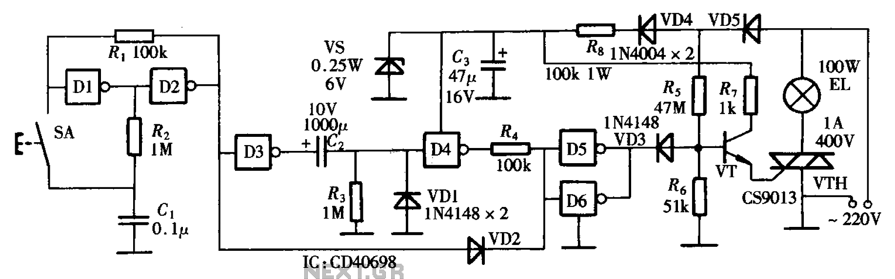
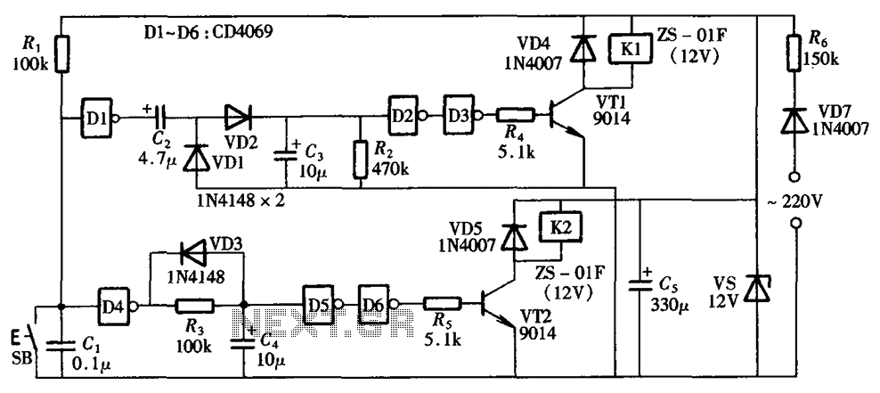
The bedside door fixture delay circuit features a straightforward design and offers cost-effectiveness. It is constructed using a hex inverter CD4069. The bedside door fixture delay circuit employs the hex inverter CD4069, which is a versatile integrated circuit (IC) commonly...
A one-button control switch is designed to control two relays, each of which can switch the load power on and off as needed. The circuit primarily consists of a hex inverter CD4049 and two self-locking DC relays. The circuit utilizes...