
ultrasonic sensor interfacing with 8051

The operation of an ultrasonic sensor involves several steps:
1. Set the "Trig" pin of the sensor high for 10 µs to initiate a sensor cycle.
2. The sensor's transmitting piezo transducer sends out 8 pulses at a frequency of 40 kHz, after which the "Echo" pin transitions from low to high.
3. The emitted 40 kHz sound wave reflects off the nearest object and returns to the sensor.
4. Upon detecting the reflected sound wave, the Echo pin returns to a low state.
5. To interface the sensor with the AT89S51 microcontroller, two I/O pins are required: one for an external interrupt pin (INT0 or INT1) to measure the pulse width at the echo pin, and another pin, such as P3.5, for the trigger.
6. Configure TIMER0 of the 8051 microcontroller in 16-bit mode with the GATE bit enabled. When the GATE pin is enabled and the timer run control bit TR0 is set, TIMER0 will be controlled by the INT0 pin. TIMER0 starts counting when INT0 is high and holds its count when INT0 goes low. The TMOD register should be loaded with the value 00001010 (0x0A), as referenced in 8051 documentation.
The ultrasonic sensor's design and implementation in a robotic application involve careful consideration of the interfacing with the microcontroller, as well as the timing and pulse width measurement for accurate distance calculation. The use of TIMER0 allows for precise timing control, essential for effective distance measurement. By enabling the GATE function, the timer can be synchronized with the interrupt signals, ensuring that the timing of the echo pulse is accurately captured. This method of operation provides reliable object detection capabilities, making ultrasonic sensors a preferred choice for robotic applications requiring environmental awareness.If you want to make your robot sense the objects in it`s surroundings i suggest you to go for an ULTRASONIC sensor. Though the IR based sensors are cheep, their working range may vary due change in ambient light and won`t give accurate range values.
In case of ULTRASONIC sensors they work based on the principle of RADAR(RAdio Detection And Ranging). A RADAR transmits electromagnetic "pulse" towards the target and receives the "echo" reflected by the target. Then the range of the target is determined by the "time lagging" between transmitted pulse and the received "echo".
Generally microwave and ultrasonic frequencies are used in RADARS STEP1. Make "Trig" pin of the sensor high for 10 µs. This initiates a sensor cycle. STEP2. 8 x 40 kHz pulses will be sent from the transmitting piezzo transducer of the sensor, after which time the "Echo" pin on the sensor will go from low to high. STEP3. The 40 kHz sound wave will bounce off the nearest object and return to the sensor. STEP4. When the sensor detects the reflected sound wave, the Echo pin will go low again. STEP6. To inter face the sensor to AT89S51 microcontroller we need two I/O pins. One of them is external interrupt pin(INT0 or INT1) for measuring the pulse width at the echo pin. and any other pin say P3. 5 for trigger. STEP3. Configure the TIMER0 of 8051 in 16 bit mode with GATE bit enabled. If the GATE pin is enabled and timer run control bit TR0 is set, the TIMER0 will be controlled by INT0 pin.
When INT0 is high then the TIMER0 starts counting. Whenever INT0 goes low TIMER0 holds its count. So load the TMOD register with 00001010=0x0A; (better refer to any book of 8051). 🔗 External reference
Related Circuits
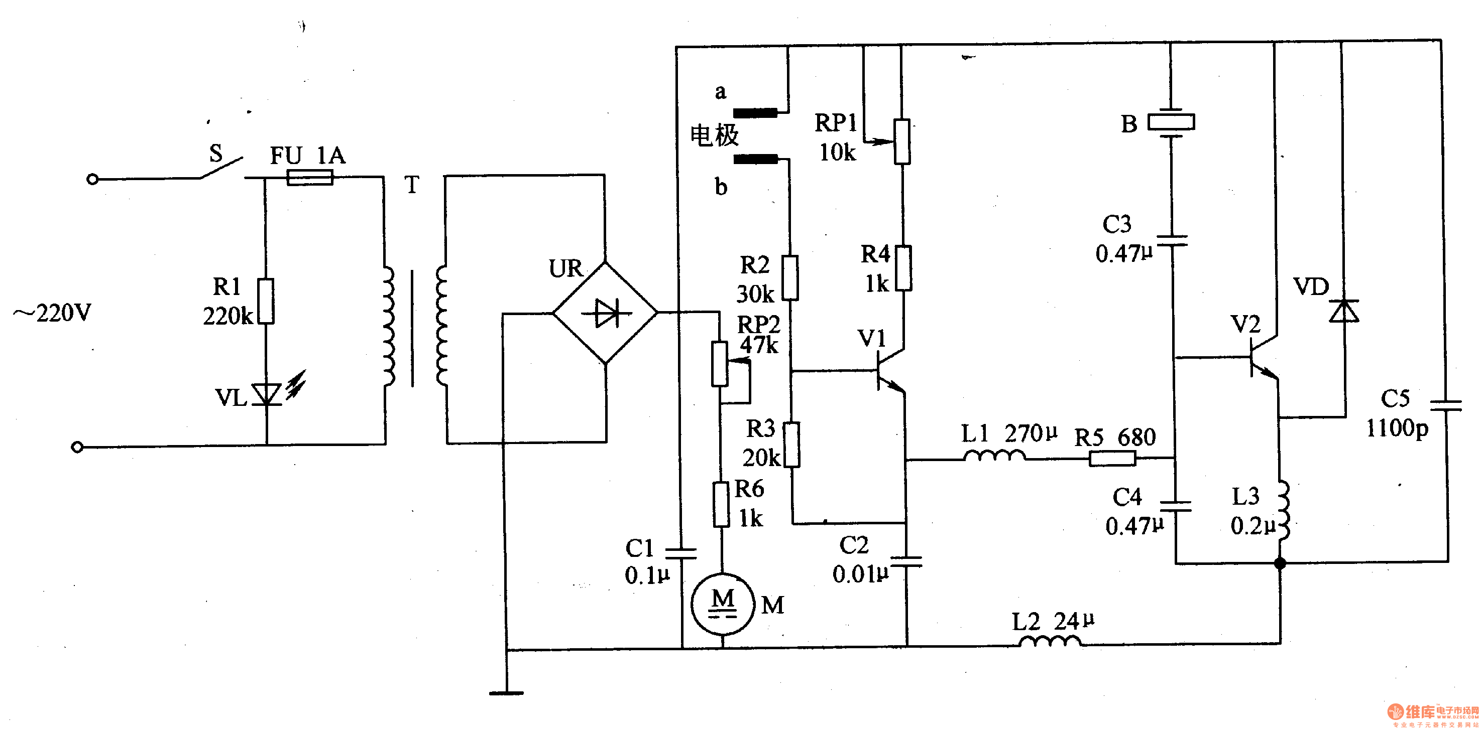
The medical ultrasonic atomizer circuit consists of a power supply circuit, a low side liquid level protection control circuit, an ultrasonic oscillator, and a fan drive circuit, as depicted in figure 9-112. The power supply circuit includes a power...

This line-following robot sensor, also known as a surface scanner for robots, is a compact, stamp-sized infrared proximity detector designed for short-range detection, typically within 5 to 10 mm. The line-following robot sensor operates using infrared light to detect the...
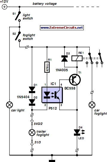
A rear fog lamp is mandatory for trailers and caravans to enhance visibility during foggy conditions. When the fog lamp is activated, the fog lamp of the towing vehicle must be turned off to prevent distracting reflections. To achieve...
The general-purpose circuit of the simple pressure sensor alarm is constructed using a few easily accessible and inexpensive components. The operation of this circuit is straightforward. The simple pressure sensor alarm circuit typically includes a pressure sensor, an operational amplifier...
The purpose of this circuit is to animate shop windows using a capacitive sensor placed behind a postcard-like banner. The card is positioned against the glass inside the shop window, allowing visitors to activate the relay by placing their...
Here is an interesting circuit for a magnetic proximity switch which can be used in various applications. The magnetic proximity switch circuit, in principle, consists of a reed switch at its heart. When a magnet is brought in the...