
Magnetic proximity sensor / detector

The magnetic proximity switch circuit employs a reed switch as the primary sensing element, which is a sensitive component that closes its contacts in the presence of a magnetic field. This action is crucial as it initiates the operation of the entire circuit. The reed switch is typically of the normally open type, meaning it remains open until a magnet is introduced nearby. This feature allows for a wide range of applications, including security systems, automation devices, and proximity sensing in various electronic projects.
In this design, the reed switch is connected to a timer IC, specifically configured in monostable mode. This configuration ensures that when the reed switch closes, it triggers the timer, causing its output at pin 3 to go high for a predetermined period. The timer's output serves as a clock signal for the subsequent flip-flop stage, which is implemented using the CD4013 dual D-type flip-flop. The flip-flop is set up in toggle mode, where the output state changes with each clock pulse received.
The output from the flip-flop at pin 2, which is the Q output, is connected to a relay driver transistor (T1). When the flip-flop toggles its state to high, it forward-biases the transistor, allowing current to flow through the relay (RL1). This energizes the relay, which can then control a larger load or switch other devices within the system.
An LED (D2) is included in the circuit as a visual indicator of the system's operation. When the relay is energized, the LED illuminates, providing immediate feedback that the magnetic proximity switch has been activated. This indicator is particularly useful for troubleshooting and confirming the circuit's functionality during testing.
Overall, this magnetic proximity switch circuit is effective for applications requiring non-contact sensing and can be easily adapted for various uses by modifying the timer duration or the load connected to the relay. The simplicity and reliability of the components make it a suitable choice for both hobbyists and professionals in the field of electronics.Here is an interesting circuit for a magnetic proximity switch which can be used in various applications. The magnetic proximity switch circuit, in principle, consists of a reed switch at its heart. When a magnet is brought in the vicinity of the sensor (reed switch), it operates and controls the rest of the switching circuit.
In place of the reed switch, one may, as well, use a general-purpose electromagnetic reed relay (by making use of the reed switch contacts) as the sensor, if required. These tiny reed relays are easily available as they are widely used in telecom products. The reed switch or relay to be used with this circuit should be the normally open type. When a magnet is brought/placed in the vicinity of the sensor element for a moment, the contacts of the reed switch close to trigger timer IC1 wired in monostable mode.
As a consequence its output at pin 3 goes high for a short duration and supplies clock to the clock input (pin 3) of IC2 (CD4013 dual D-type flip-flop). LED D2 is used as a response indicator. This CMOS IC2 consists of two independent flip-flops though here only one is used. Note that the flip-flop is wired in toggle mode with data input (pin 5) connected to the Q (pin 2) output.
On receipt of clock pulse, the Q output changes from low to high state and due to this the relay driver transistor T1 gets forward-biased. As a result the relay RL1 is energised. 🔗 External reference
Related Circuits
Many individuals install motion detectors in their backyards or homes to automatically turn on lights when movement is detected. Motion sensor lights have gained popularity and are increasingly utilized in various settings. Businesses frequently employ them in bathrooms, where...
This is a simple sound sensor schematic that utilizes a single integrated circuit (IC) and two transistors to drive a relay. The schematic allows for sensitivity adjustment using a variable resistor (VR). This design is quite useful and can...
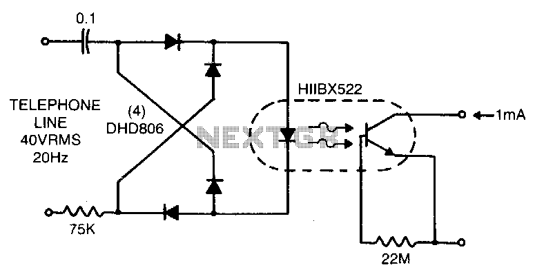
Low line current loading is provided by the H11BX522 photodarlington optocoupler, which delivers a 1 mA output from a 0.5 mA input. The H11BX522 is a photodarlington optocoupler that is designed to provide electrical isolation between its input and output...
The purpose of this circuit is to animate shop-windows by means of a capacitive sensor placed behind a post-card-like banner. The card is placed against the glass inside the shop-window, and the visitor can activate the relay placing his...

VCR Camera Video Detector Switch Controller Circuit. This video detector switch controller circuit utilizes the video output from a VCR or camera to... This circuit functions as a video detector switch controller, designed to manage the video output from a...
The UHF motion detector operates on the Doppler radar principle. An oscillating signal is generated by the oscillator (Q1), and a portion of this energy is reflected back. The UHF motion detector employs the Doppler radar principle to detect motion...