
Clamp meter circuit

To use a clamp ammeter effectively:
1. Zero Adjustment: Before measuring current, ensure the display reads zero. If not, use a small screwdriver to adjust the zero point until the needle indicates zero, enhancing measurement accuracy.
2. Range Selection: Choose the correct measurement range based on the expected current size. It is crucial to avoid using a small range for large currents. Adjust the range switch to the appropriate position before commencing measurement.
The handheld design features a Bakelite handle. To measure current, the index finger is used to tighten the core switch, allowing the core to be positioned around the lead wire. Once the core is in place, releasing the switch allows it to close around the conductor. The alternating magnetic field generated by the current induces a current in the meter, which can be read directly.
The clamp meter is a versatile tool in electrical diagnostics, providing non-intrusive current measurements. Its design allows for quick and efficient measurements in various applications, making it essential for electricians and engineers. The use of a feedthrough current transformer ensures accurate readings, while the zero adjustment feature enhances precision. Proper range selection is critical to prevent damage to the meter and ensure reliable measurements. The ergonomic design of the handle facilitates ease of use in tight spaces, making it suitable for both professional and DIY applications.Ammeter measuring current in the circuit, the need to break the circuit in series in the circuit to be measured. The clamp meter without the need for the case to break the circ uit, it can be measured directly in the line of electrical flow. As shown in Figure 5-1 Clamp Meter shape and circuits. (1) structural principle clamp current clamp meter Yuans main component is a feedthrough current transformer. When measuring the electrical clamp magnet flow table set in the lead wire, thereby forming a line of turn circle, according to the principle of electromagnetic induction, the secondary coil will produce induced current ammeter pointer, and the second line is connected to the network it will lead to the partial transfer, indicating the value of the line current.
Use (2) Clamp ammeter 1 Zero bits: Before measuring current, to see whether the hands refers to zero, if not zero means the application of a small screwdriver to adjust the head table of zero point zero bolt so hands bit, in order to improve the reading registration accuracy. 2) Select the stalls: When using a clamp meter to select the correct gear. Should estimate the size of the measured current before measurement, select the appropriate amount of drive is not available to a small range for measuring large currents.
When measured using the range switch to the appropriate position. Handheld bakelite handle. Hook with the index finger tight core switch to turn the core, the core gap from the lead wire is introduced to the central core. Then, relax hook index finger tight core switch, core self-closing, the measured conductor current alternating magnetic field lines generated in the core, there will be induced currents on the table, it can be directly read.
Related Circuits

The circuit operates by processing an input signal through IC1-1 and a fourth-order low-pass filter, which provides a slope of 24 dB/octave with a cutoff frequency (fc) of 70 Hz and an amplification of 8.2 dB. The output from...
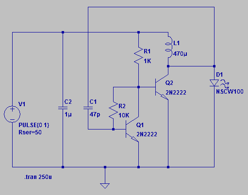
Four observations regarding the Joule Thief AA battery LED circuit. The schematic of the LED circuit illustrates the power source (V1), which symbolizes a depleted battery with only 1 volt remaining and an internal resistance. The Joule Thief circuit is...
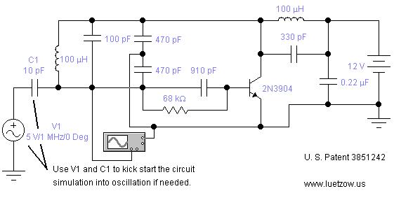
The oscillator circuits presented on this page are derived from expired or non-maintained U.S. Patents. All circuits are formatted for "Electronic Workbench 5.12" or "Multisim 7" circuit simulation software. A note regarding SPICE simulation of electronic oscillator circuits: all...
Normally the base of a cordless phone has an adaptor and the handset has Ni-Cd cells for its operation. The base unit becomes inoperative in case of power failure. In such conditions, it is better to provide a backup...
This is an easy-to-build yet highly accurate digital voltmeter designed as a panel meter. It can be utilized in DC power supplies or any application requiring precise voltage readings. The circuit uses the CL7107 Analog to Digital Converter (ADC)...
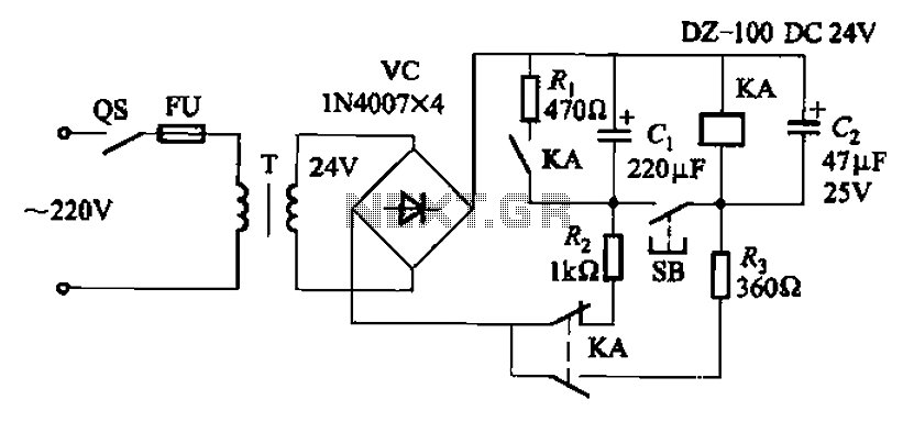
After the turn-off circuit is first applied to the next KA KA, the intermediate interval required is less than Is. This is due to the time needed, which is equal to three times the charge time constant of the...