
Inductive Electronic Oscillator Circuit

The provided oscillator circuits utilize various configurations to generate oscillatory signals, which are essential in numerous applications including signal generation, timing, and frequency modulation. The circuits can be analyzed and simulated using Electronic Workbench 5.12 or Multisim 7, both of which are robust platforms for electronic circuit simulation.
In these simulations, users can observe the behavior of the oscillator circuits in real-time, allowing for a thorough understanding of their performance characteristics. The circuits typically consist of active components such as operational amplifiers, transistors, or integrated circuits, along with passive components like resistors, capacitors, and inductors, which together establish the feedback necessary for oscillation.
The selection of position sensing oscillators indicates a focus on circuits that can detect and respond to physical position changes, which can be particularly useful in applications like robotics, automotive systems, and automation technology. As these patents have expired, the circuits can be freely utilized and modified, promoting innovation and development in the field of electronics.
For users experiencing difficulties with oscillation in their simulations, it is advisable to verify component values, connections, and the overall configuration of the circuit. Each simulator may have unique settings or limitations that could affect the circuit's performance. Therefore, consulting the documentation for the specific simulation software being used can provide additional insights into troubleshooting and optimizing circuit behavior.The oscillator circuits presented on this page are from expired or non-maintained U. S. Patents. All circuits are presented in "Electronic Workbench 5. 12" or "Multisim 7 circuit simulation formats". A note on spice simulation of electronic oscillator circuits. All of the oscillator circuits presented on this web page have been simulated using eithe r Electronic Workbench 5. 12 or Multisim 7 electronic spice programs. All of the circuits will oscillate using the simulator schematics as shown. It is unknown if the circuits will oscillate on other brands of spice circuit simulators. If you have problems getting your circuit to oscillate on your simulator, You can to email questions to me at bob@luetzow. us. This web page is basically about electronic oscillator circuits and how to demonstrate the circuit`s oscillating functions using spice software.
The position sensing oscillators were selected because they are all expired patents and are in the public domain. 🔗 External reference
Related Circuits
Half of a Motorola MG14538B dual precision retriggerable monostable multivibrator is utilized to create an extended on-time timer circuit. This type of circuit can function as a switch debouncer. Such circuits are commonly implemented in digital applications, where every...

RTD sensors are measured using a precision 24-bit analog-to-digital converter (A/D) that includes a built-in programmable gain amplifier. The connections for 2-wire, 3-wire, and 4-wire RTDs are illustrated. This setup facilitates the connection and measurement of RTDs with amplifiers and...
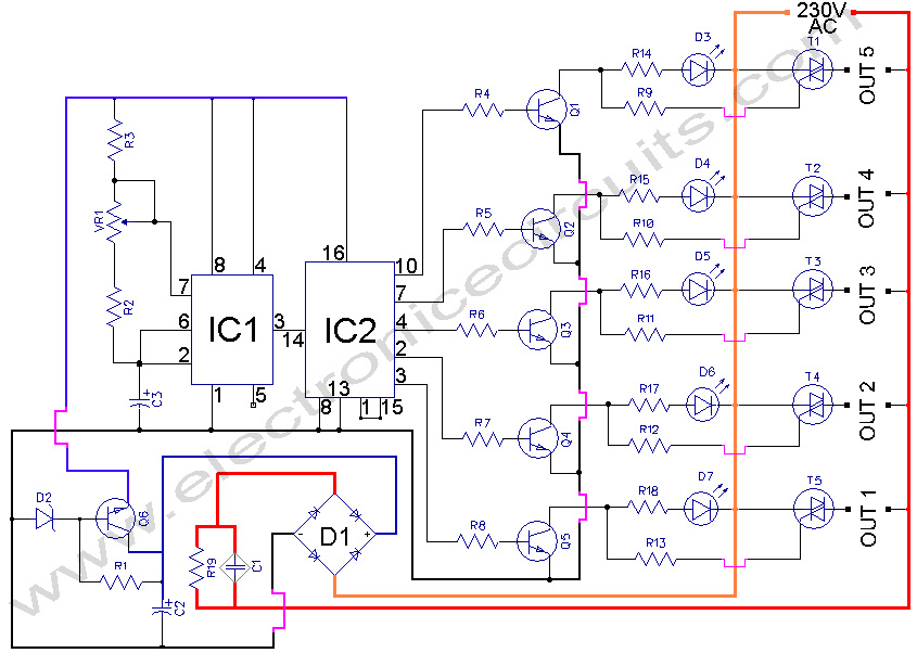
5 WAY AC FLASHER. These types of circuits are commonly used in various ceremonies such as the Wesak festival, Christmas, and weddings. This 5 WAY AC FLASHER circuit. The 5 Way AC Flasher circuit is designed to produce a sequential...
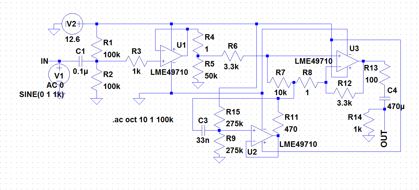
A circuit was required to function as a bass boost. The design was adapted from a circuit by ESP Sound, focusing solely on the frequency range of 35-150 Hz. The bass boost circuit, as adapted from the original design, primarily...
Color sensing using a camera and a sufficiently powered processor that runs image histogram logic (or similar algorithms) can reliably determine the presence of specific colors. However, alternatives that are significantly more cost-effective for detecting the presence or absence...

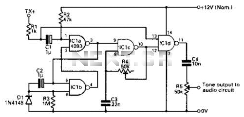
This is the design circuit diagram of an ultrasonic mosquito repeller. The circuit operates based on the theory that insects, such as mosquitoes, can be repelled by sound frequencies in the ultrasonic range (above 20 kHz). The circuit utilizes...