
Clap switch circuit

The clap switch circuit operates by detecting the sound of a clap through a condenser microphone. This microphone converts sound waves into an electrical signal, which is then processed by the circuit. The internal FET of the microphone is biased by resistor R1, ensuring that it operates within its optimal range to detect sound effectively.
Once the sound is detected, the initial signal is amplified by transistor T1. This amplification is crucial because it strengthens the weak signal generated by the microphone, allowing it to be further processed by subsequent stages. Transistors T2 and T3 continue the amplification process, ensuring that the signal reaches a sufficient level for the control functions to be executed.
Transistor T4 plays a pivotal role in the circuit, acting as a switch that controls the relay. When the amplified signal meets a certain threshold, T4 is activated, allowing current to flow to the relay coil. This action closes the relay contacts, thereby enabling the connected load, such as a light or fan, to turn on or off based on the sound input.
The relay used in this circuit is vital for controlling higher power loads, as it isolates the low-power control circuit from the high-power devices. The specifications of the relay, including its contact ratings, determine the types of loads that can be controlled. The schematic provides a visual representation of the connections and components within the circuit, illustrating the pathways through which the electrical signals flow.
In summary, this clap switch circuit exemplifies the effectiveness of simple electronic components to create a functional device capable of controlling various appliances through sound detection. Its design emphasizes the potential of basic circuits to fulfill complex operational roles without the need for more advanced components.This clap switch can turn on and off a light, fan, music system, alarm. virtually any gadget, at the sound of a clap. The most amazing part of the design is that it gives an a efficient two state control without employing any op amp, any counters, timers or flip-flops but just four transistor. The design shows how basic circuits can do complex jobs. The so und is sensed by a small button microphone(condenser microphone)whose internal FET is biased by R1. The signal is amplified by T1, T2, T3, andT4 provides the remaining control functions. There isn`t much to explain but much can be understood by carefully observing the design. T4 drivers a relay. The relay is further used to control the load as shown in schematic b. It is the contacts of the relay that determine the loads that it can handle. 🔗 External reference
Related Circuits
This document presents a collection of engaging and challenging electronic circuits that can be built for enjoyment. The author has a long-standing passion for electronics, having studied the subject since middle school and developed numerous circuits over the years....
Visit eBid United Kingdom, the online marketplace without fees - buy and sell today. eBid United Kingdom serves as an online marketplace that facilitates buying and selling transactions without imposing fees on its users. This platform offers a user-friendly interface...
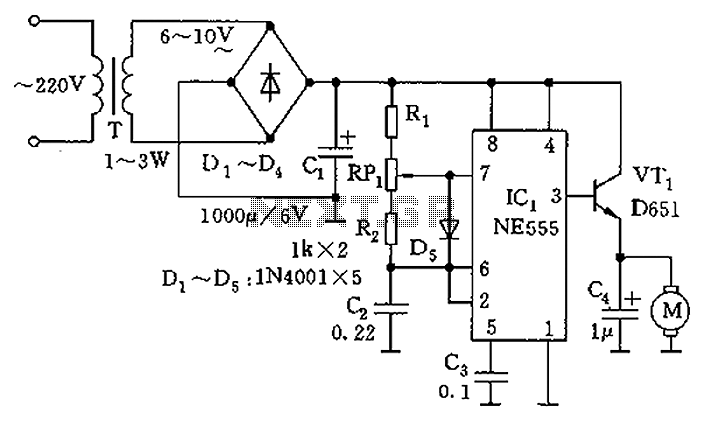
The circuit utilizes a 555 timer as the core component to create an astable multivibrator. The oscillation period T is given by the formula T = 0.693 (R1 + 2R2) C1, which corresponds to an oscillation frequency of approximately...
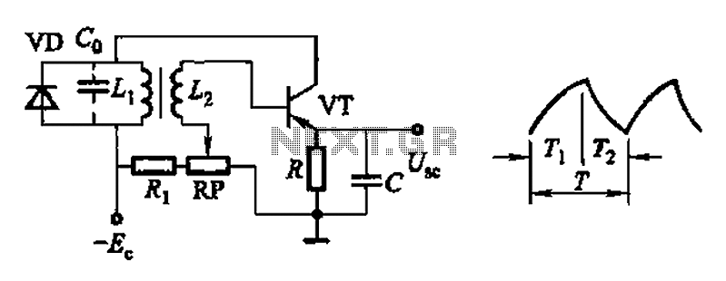
Common non-sinusoidal oscillator circuit, waveform and frequency formula - pulse wave oscillator - single-junction transistor blocking oscillator. The common non-sinusoidal oscillator circuit described is a pulse wave oscillator that utilizes a single-junction transistor in a blocking configuration. This type of...
This compact device, designed primarily for modelers, provides instantaneous readings of pulse duration in milliseconds (ms). It can measure servomotor positions, typically ranging from 1 ms to 2 ms, and can also perform repetitive or non-pulsed measurements, such as...
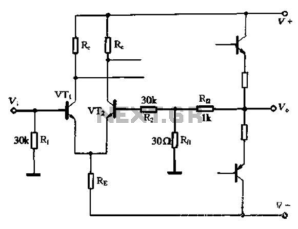
The circuit utilizes the configuration illustrated in Figure 1-36, with the feedback circuit and bias circuit implemented separately. The feedback resistor, Rfl, is approximately 30 ohms. To maintain the desired amplification, the resistor R queue is set to 1...