
Super audio Reverb

In this circuit modification, the original design underwent significant changes where blue values were substituted with corresponding red values to enhance performance or compatibility. The removal of blue components indicates a strategic decision to eliminate elements that may have been outdated or inefficient, thereby streamlining the circuit's functionality. The introduction of red components signifies the incorporation of new elements that are likely to improve the circuit's overall efficiency, reliability, or operational capabilities.
The schematic should reflect these changes clearly, with all blue components removed and replaced with appropriate red components. Each component's specifications, such as resistance, capacitance, or inductance, should be accurately updated to reflect the new red values. This ensures that the circuit operates within the desired parameters and meets the intended design requirements.
For clarity, all connections must be reviewed to ensure that the new components are integrated correctly with the existing circuit layout. Careful attention should be given to the orientation of polarized components and the ratings of all new parts to prevent circuit failure. Additionally, simulation of the modified circuit is recommended to verify performance under expected operating conditions and to identify any potential issues arising from the changes made.Blue VALUES replaced by values in RED. Blue COMPONENTS removed from circuit. Red components added to circuit. 🔗 External reference
Related Circuits

This circuit design for an amplifier was created to address the gap in the 3-10 Watts power output range of audio amplifiers available in RED Free Circuit Designs. A straightforward, low-component-count amplifier was developed based on the successful 45...
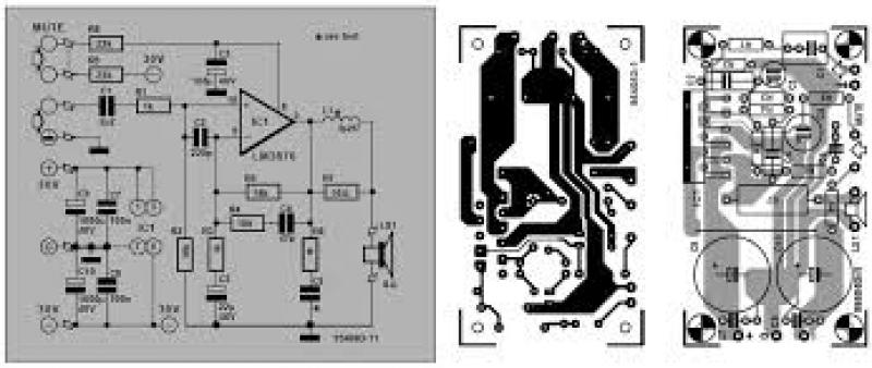
The air-cored inductor L1 is constructed using 13 turns of 1mm diameter enamelled copper wire, featuring an inner diameter of 10mm. The completed inductor is positioned over R7, with its terminals soldered to those of the resistor. All electrolytic...
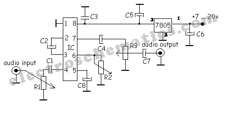
A simple audio compressor is designed using the SSM2165 integrated circuit (IC). There is limited explanation available regarding the schematic of this compressor circuit; however, special attention should be given to the capacitor used. The audio compressor circuit utilizing the...
This weblog focuses on electronic circuit schematics, PCB design, DIY kits, and diagrams for various electronic projects. It features a mixer that demonstrates how to create microphone pre-amplifiers suitable for both low and high impedance microphones. The design utilizes...
Wind 6 turns of solid wire on a pen or pencil that is just under 1/2 inch in diameter. Remove the wire from the pencil and spread the winding to make a length of 3/4 inch. Solder C2 somewhere...
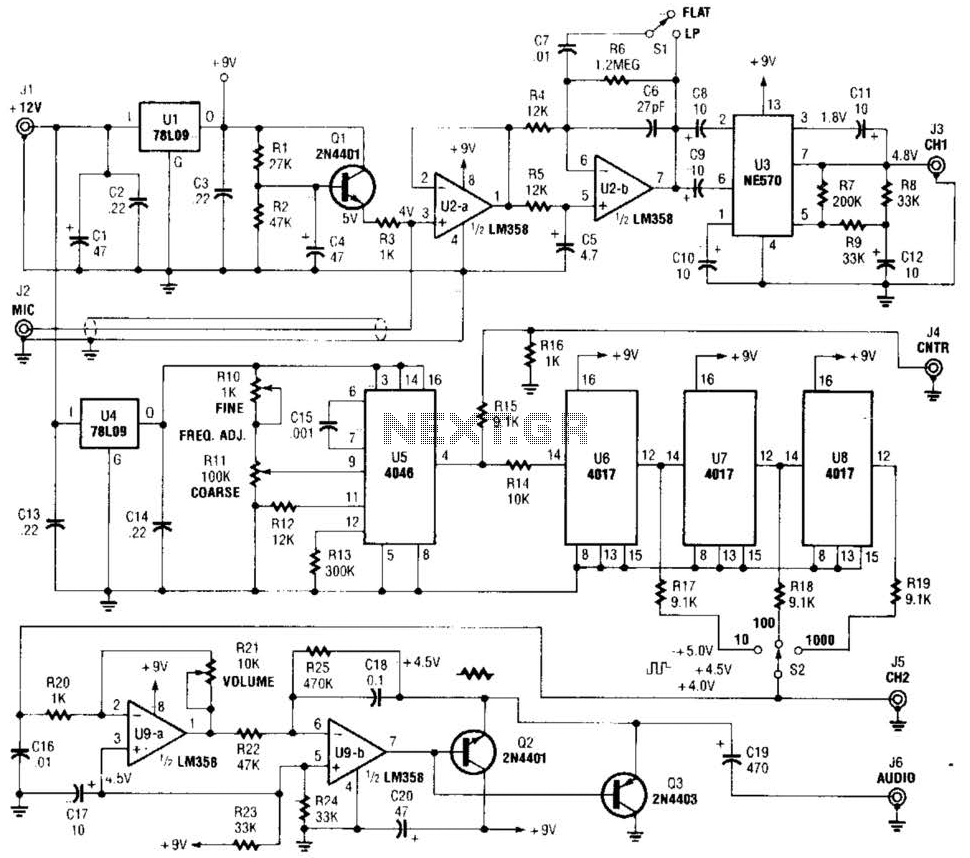
The precision audio frequency generator consists of several sub-circuits: an audio amplifier/filter circuit, an automatic level control, a variable voltage-controlled oscillator, a frequency divider circuit, an integrator, and an audio output amplifier. An electret microphone element is utilized to...