
555 electronic musical instrument additional combo audio circuit
The combination audio circuit integrates an astable multivibrator configuration utilizing the 555 timer IC, which is a widely used component in timing applications. The astable multivibrator operates continuously, generating a square wave output that can be used to trigger audio signals corresponding to drum and cymbal sounds.
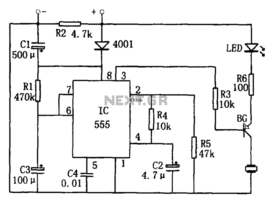
In this setup, R1, RP1, and R2 are resistors that determine the frequency of the oscillation, while C1 is a capacitor that influences the timing characteristics of the output waveform. The values of these components can be adjusted to modify the tempo and rhythm of the generated sound, allowing for flexibility in performance.
The output from the 555 timer can be connected to a sound synthesis module or a digital audio processor that generates the desired drum and cymbal sounds. By adjusting the duty cycle of the square wave, the audio circuit can create varied sound dynamics, enhancing the expressiveness of the musical performance.
Additionally, the implementation of this audio circuit can involve further components such as operational amplifiers for signal conditioning, filters to refine the audio output, and possibly a mixer stage to balance the levels of the drum and cymbal sounds. This comprehensive approach ensures that the audio output is not only synchronized with the rhythm generator but also meets the quality expectations of contemporary electronic music performance.If we add this combo audio circuit (as the figure 14-38 shows) to the automatic rhythm generator of the electronic musical instruments, we can meet the the requirements of players to add the combo audio of drum and cymbals to make the performance effect more perfect. As the figure shows, the astable multivibrator is composed of the 555 and R1, RP1, R2, C1,.. 🔗 External reference
Related Circuits
The development of the entire system necessitated a thorough identification of all processes related to the laser controller. The initial diagram outlines the primary physical components utilized in the CNC laser system. The setup includes a power supply, a...

The ramp voltage from the low-frequency oscillator IC1 modulates IC2, thereby producing a rising and falling tone similar to the wail of police cars. The described circuit utilizes a low-frequency oscillator (IC1) to generate a ramp voltage. This ramp voltage...
This article outlines the construction of a simple microcontroller-based delay circuit designed for photographic applications such as drop or high-speed photography. It can control the trigger lag of cameras and flash units, generate periodic trigger pulses, or manage magnetic...
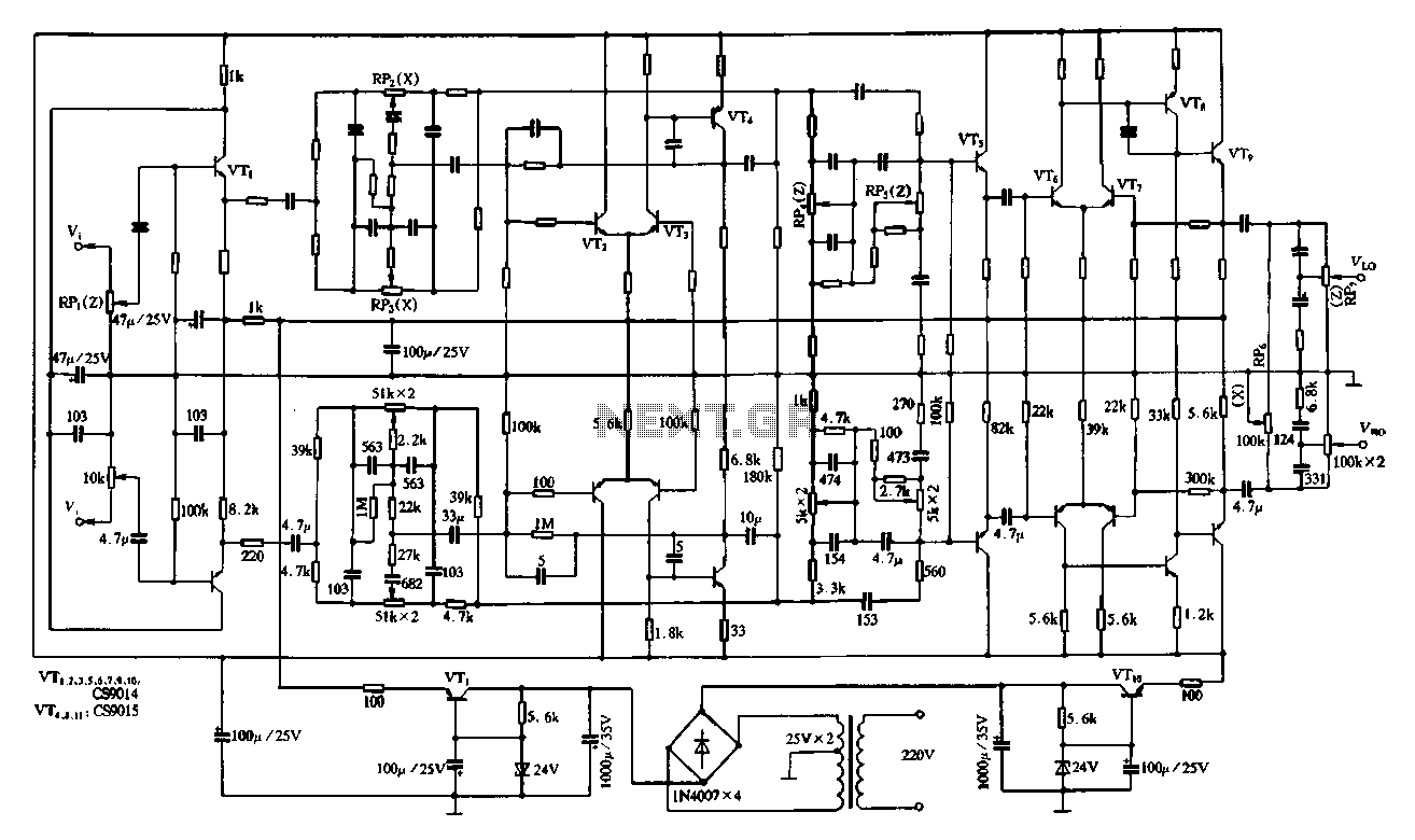
Figure 4-11 illustrates a feedback attenuator that comprises a transistor-based tone control circuit. This circuit features a conventional high and bass control system, along with balance control, volume control, loudness adjustment, and subwoofer control, as well as field sense...

This project was completed successfully, achieving the desired frequency and strength. For assistance, please reach out for support in resolving any issues. The project involves the design and implementation of an electronic circuit that operates at a specified frequency and...
The circuit is designed to provide a reminder for lights using a monostable delay configuration. It comprises a monostable delay circuit, a driving circuit, a buzzer, light-emitting diodes (LEDs), and other components. The output signal from the delay circuit,...