
Class E AM Transmitter for 1710 kHz

The 200-watt class-E AM transmitter operates at a frequency of 1710 kHz, which is in the medium wave AM broadcast band. Class-E amplifiers are known for their high efficiency, typically exceeding 80%, which makes them suitable for applications requiring significant power output with minimal heat generation. In this design, the transmitter utilizes a negative peak limiter to prevent distortion during high modulation peaks, ensuring audio quality remains intact while transmitting.
The over-modulation indicator serves as a critical feature, alerting the operator when the modulation level exceeds acceptable limits. This is essential for maintaining compliance with broadcasting standards and preventing interference with adjacent channels. The linear scale directional wattmeter included in the schematic allows for accurate measurement of the transmitter's output power, facilitating adjustments to ensure optimal performance.
Power supply circuits are integral to the operation of the transmitter, providing the necessary voltage and current to the amplifier stages. The design may incorporate voltage regulation and filtering components to ensure stable operation under varying load conditions. Additionally, the antenna circuits facilitate efficient radiation of the transmitted signal, which is crucial for effective broadcasting.
Overall, this transmitter design combines advanced features to achieve reliable and high-quality AM broadcasting, while also addressing the need for monitoring and compliance with broadcasting regulations.A 200-watt class-E AM transmitter used for non-sanctioned broadcasting on 1710 kHz. Negative peak limiter, over-modulation indicator, linear scale directional wattmeter, power supply and antenna circuits (schematic diagram) are also shown.. 🔗 External reference
Related Circuits
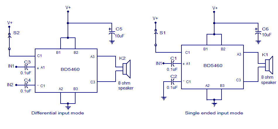
The BD5460 is a low power Class D amplifier that can be utilized in low power applications such as handheld audio devices. The BD5460 does not require an LC filter at the speaker output and can be powered by...
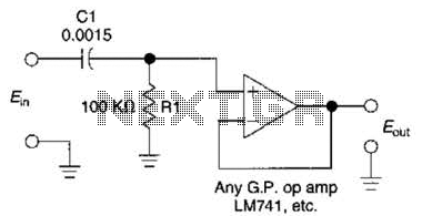
This simple 1 kHz filter utilizes a voltage follower and an RC section as its filtering element. For other frequencies, the -3 dB point is given by the formula 1/(6.28 Rl Cv), and the response decreases at a rate...
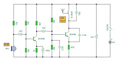
This is a mini FM transmitter circuit that utilizes two transistors. The audio sensitivity is notably high when paired with an ECM type microphone. The transmitter operates using a Hartley oscillator configuration. Typically, the capacitor in the tank circuit...
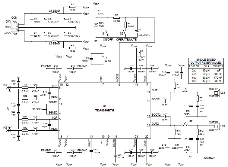
This high-power Class D audio amplifier electronic project is designed using the TDA8920BTH audio power amplifier IC. This power amplifier IC offers very high efficiency with minimal dissipation, yielding significant output power. The typical output power is 200 watts...
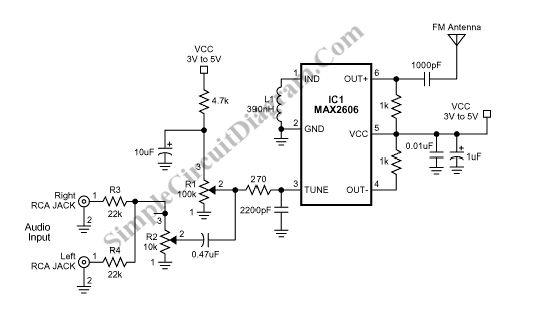
The FM transmitter circuit operates within the broadcast band of 88 to 108 MHz and can be utilized to transmit audio signals for remote listening. The output power... The FM transmitter circuit is designed to function within the frequency range...
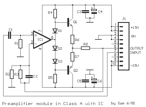
The original description discusses an application that is reputed for its high-quality sound. This superior sound quality is attributed to the operation of the entrance transistors at Class A. The sound quality is largely dependent on IC1, which needs to...