
bd5460 class d amplifier circuit

The BD5460 Class D amplifier is designed for efficiency and compactness, making it an excellent choice for portable audio applications. Its ability to operate without an LC filter simplifies the design and reduces the overall component count, making it suitable for space-constrained environments. The amplifier's output capability of 0.8 watts into an 8-ohm load at a nominal voltage of 3.6 V allows for adequate audio performance in small devices, such as portable speakers and handheld gaming consoles.
The integrated standby function is particularly advantageous for battery-operated devices, as it helps to conserve power when the amplifier is not in use. The zero standby current ensures that battery life is maximized, which is critical in portable applications. The built-in short circuit protection and thermal shutdown features provide additional reliability, safeguarding the amplifier from damage due to overload conditions.
The circuit design includes two configurations for the BD5460, allowing designers to choose between a differential input and a single-ended input setup based on the application's requirements. The use of 0.1 µF decoupling capacitors is crucial for maintaining signal integrity by filtering out unwanted DC offsets and noise, which can affect the amplifier's performance. The 10 µF capacitors serve to stabilize the power supply, ensuring that the amplifier receives clean power for optimal operation.
Shutdown switches S1 and S2 provide a simple method to control the amplifier's operation. By toggling the C1 pin between a high logic level and ground, users can easily switch the amplifier on and off, enhancing user control over the device's power state.
Overall, the BD5460 is a versatile and efficient Class D amplifier that meets the demands of modern low-power audio applications, providing a reliable solution for designers seeking to implement high-quality audio in compact electronic devices.BD5460 is a low power {lass D amplifier that can be employed in low power applications like handheld audio devices. BD5460 doesn`t need an LC filter at the speaker output and can be driven employing a battery, The standby current of BA5460 is usually zero and there`s no switch on / OFF clicks.
The BD5460 can deliver 0. 8 watts into an 8 ohm speaker at 3. 6 V supply voltage. the power supply voltage range is from 2. 5 to 6. 5 V DC. The IC contains a built-in standby function, short circuit protection, thermal shutdown and below voltage lockout. Two class D amplifier circuits using BD5460 are shown here. the first one is a differential input class D amplifier while the second one is a single ended input class D amplifier.
The 0. 1uF capacitors (C1, C2, C3 and C4) are input DC decoupling capacitors. The lower interrupt frequency of the amplifier depends on these capacitors. 10uF capacitors (C5 and C6) are the power supply filters. S1 and S2 are the shutdown switches. Connecting the C1 pin to the high logic can create the IC active and connecting the C1 pin to ground will put the Ic into shutdown mode. 🔗 External reference
Related Circuits
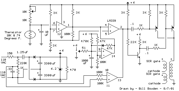
The heating element is connected in series with two back-to-back 16 amp silicon-controlled rectifiers (SCRs), which are controlled by a small pulse transformer. This pulse transformer features three identical windings; two of these windings provide trigger pulses to the...
The voice recorder's entry information can be stored for 100 years, repeated 100,000 times, with low power consumption. It requires a 5-6V DC power supply and has a recording current of 2 mA. The voice recorder circuit is designed to...
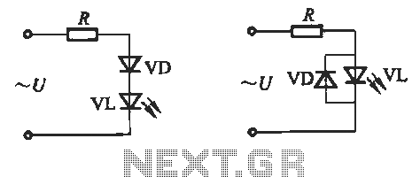
Light-emitting diodes (LEDs) can be powered using direct current (DC), alternating current (AC), and pulse drivers. A typical buck LED display circuit is illustrated in Figure 13-1. The current-limiting resistor (R) for LED tubes can be calculated using the...
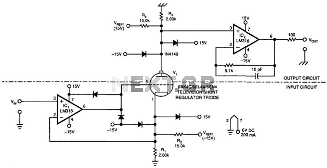
This amplifier can transfer DC to 5 MHz signals across a potential difference of 25,000 V. It can be utilized in CRT displays and high-voltage applications. It is important to note that the tube must be shielded due to...
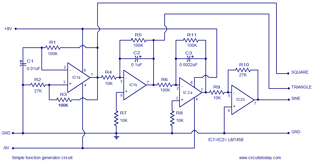
A simple function generator circuit utilizing the LM1458 is presented here. The LM1458 is a dual general-purpose operational amplifier. The two op-amps within the LM1458 share a common bias network and power supply line, yet operate independently. The function generator...
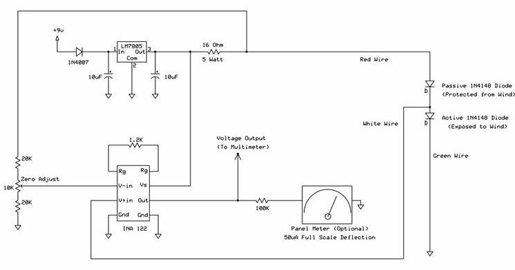
The following circuit illustrates a wind speed indicator circuit. It operates with a constant 5 VDC output provided by the LM7805 voltage regulator, using a 9 VDC supply. The wind speed indicator circuit is designed to measure and display wind...